Download
1 / 3
230 likes | 607 Vues
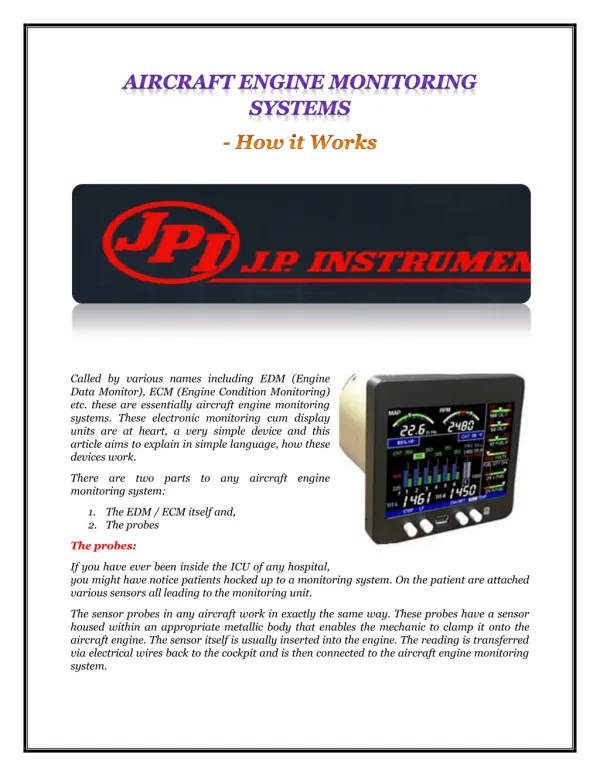
The sensor probes in any aircraft work in exactly the same way. These probes have a sensor housed within an appropriate metallic body that enables the mechanic to clamp it onto the aircraft engine. The sensor itself is usually inserted into the engine. The reading is transferred via electrical wires back to the cockpit and is then connected to the aircraft engine monitoring system.

E N D
Called by various names including EDM (Engine Data Monitor), ECM (Engine Condition Monitoring) etc. these are essentially aircraft engine monitoring systems. These electronic monitoring cum display units are at heart, a very simple device and this article aims to explain in simple language, how these devices work. There are two parts to any aircraft engine monitoring system: 1.The EDM / ECM itself and, 2.The probes The probes: If you have ever been inside the ICU of any hospital, you might have notice patients hocked up to a monitoring system. On the patient are attached various sensors all leading to the monitoring unit. The sensor probes in any aircraft work in exactly the same way. These probes have a sensor housed within an appropriate metallic body that enables the mechanic to clamp it onto the aircraft engine. The sensor itself is usually inserted into the engine. The reading is transferred via electrical wires back to the cockpit and is then connected to the aircraft engine monitoring system.
Any aircraft – even the single engine ones have numerous probes. In days gone by, each probe used to be connected to its specific dial in the cockpit. The cockpit therefore used to have numerous dials and indicators. These days however, the probe converts the reading into an electrical pulse which is transmitted via electrical wires to the aircraft engine monitoring system. The aircraft engine monitoring system: In absolute simple terms, the aircraft engine monitoring system has three parts to it – display, intelligent data comparison and, data storage. Display: Every EDM Monitors or ECM aims to display the data in a way that helps the pilot(s) to get the gist of what is happening inside the engines in a single glance! The data is presented graphically and in figures. Most EDM’s of today also permit the pilot to choose what is displayed and how. Standard data comparison: Most EDM / ECMs permit the pilot(s) to key in upper and lower limits for every probe. The aircraft engine monitoring system compares the incoming values to the pre-entered upper and lower limits. So, if the EGT (Exhaust Gas Temperature) is approaching or is higher than the upper limit (or lesser than the lower limit), that was keyed in, the aircraft engine monitoring system will trigger an audio-visual signal thereby gaining the pilots attention. Intelligent data comparison and analysis: Aircraft Engine Monitoring Systems can not only accept data from the probes inserted into various parts of the engine, it can also accept inputs from the GPS navigation and compare the navigation output with level of fuel in the tank. It can analyse and deduce whether there is enough fuel to complete the trip and provide this information to the pilots. If the pilot(s) change the destination the Aircraft Engine Monitor Systems will recompute fuel availability in seconds. Data storage: Aircraft engine monitoring system have built-in memory modules to store data. This stored data can be downloaded for analysis via the USB Download Box or other ports located on the aircraft engine monitoring system itself.
JPI Sales: 1-800-345-4574 714-557-3805 FAX: 714-557-9840 sales@jpinstruments.com JPI Technical Support: 1-800-345-4574 714-557-3805 support@jpinstruments.com J.P. Instruments Inc. 3185-B Airway Ave Costa Mesa, CA 9262