Download
1 / 53
530 likes | 692 Vues
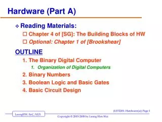
Hardware (Part B). Reading Materials: Chapter 5 of [SG]: The Computer System Optional: Chapter 2 of [Brookshear] OUTLINE Organization of a Digital Computer Major Components of a Computer System von Neumann architecture: how it fits Together The Future: non von Neumann architectures.

E N D
Hardware (Part B) • Reading Materials: • Chapter 5 of [SG]: The Computer System • Optional: Chapter 2 of [Brookshear] OUTLINE • Organization of a Digital Computer • Major Components of a Computer System • von Neumann architecture: how it fits Together • The Future: non von Neumann architectures
For Fall 2014 semester • Will only cover: • Memory unit, • ALU • CPU and Sample CPU execution • Will not cover • Cache [CJA] • Input/output, peripherals, disks storage • Control Unit • Stored program execution • Parts of Ch. 5 covered • Ch. 5.1 • Ch. 5.2.1 Memory (excluding cache memory) • Ch. 5.2.3 ALU • Ch. 5.3 (architecture diagram & example in lecture)
Introduction • Computer organization examines the computer as a collection of interacting “functional units” • Functional units may be built out of the circuits already studied • Higher level of abstraction assists in understanding by reducing complexity
Figure 5.1 The Concept of Abstraction
The Components of a Computer System • Functional units in Von Neumann architecture: • Memory • Input/Output • Arithmetic/Logic unit • Control unit • Sequential execution of instructions • One instruction at a time • Fetched from memory to the control unit • Concept of a stored program
Memory and Cache • The functional unit that stores • instructions (programs / “software”) and • Data / information • Primary Memory Types: • ROM (Read Only Memory) • Read only, permanent • RAM (Random Access Memory) • Read/Write, Volatile • Cache memory • keeps values currently in use (with faster memory)
Figure 5.3 Structure of Random Access Memory
Random Access Memory (RAM) • RAM (Random Access Memory) • Memory made of a large array of addressable “cells” (each of the same size) • Maps “addresses” to memory locations (cells) • Current standard cell size is 8 bits (byte) • All memory cells accessed in equal time • Memory address • Unsigned binary number N long • Address space is then 2N cells
a3 a2 a1 a0 00 2-to-4 DCD 01 10 11 00 01 2-to-4DCD 10 11 Rectangular RAM (impl. with Decoders) Memory Unit * size is 24 = 16 * organize as (22 x 22) rectangle 4-bit address (a3a2a1a0) split into * row address (a3a2), and * column address (a1a0) Question: Can you label the addresses of the memory locations?
1 0 0 1 00 2-to-4 DCD 01 10 11 00 01 2-to-4DCD 10 11 To access memory location 9 = (1001)2 Address = (1001)2 Row address = (10) so row with label 10 selected Column address (01) so column with label 01 selected Memory at intersection is selected Your HW: Try accessing memory locations 6, 4, 0, 15
Operations of Memory Unit • Data Transfers: • Need Instructions: • FETCH – instr to read content of a memory location (fetch some data from memory) • STORE – instr to write a value to a memory location (store some data into memory) • Need Special Registers: • MAR – for the address of the memory location; • MDR – for data to be written to / read from memory • implemented via digital circuitry • Using decoders to select individual cells • Fetch / Store decoder
What are Memory Registers (or Registers) • Memory register • Examples: MAR, MDR • Very fast memory location (1 cycle) • Given a name, not an address • Serves some special purpose • Modern computers have dozens or hundreds of registers
The “Fetch” Operation • To “read” data/info from memory • Command: Fetch (address) • Load the address of the desired memory cell into the MAR • Decode the address in the MAR • Copy content of that memory location into MDR
The Store Operation • To store information into memory • Command: Store (address, value) • Load the address into the MAR • Load the value into the MDR • Decode the address in the MAR • Store the contents of MDR into that memory location.
Figure 5.7 Overall RAM Organization
Cache Memory • Memory access is much slower than processing time • Faster memory is too expensive to use for all memory cells • Locality principle • Once a value is used, it is likely to be used again • Small size, fast memory just for values currently in use speeds computing time
Peripheral Devices (Overview) • Other Devices that augments the CPU+memory • I/O: Keyboard, mouse, monitor, printers, speakers, • Storage: Cache, Disk drives, CD-drive, Zip-drive, tapes • Communication: Network cards, modems, • Devices communicate with CPU via controllers • usually some kind of circuit board (eg: sound cards) • Also, • I/O devices vary greatly • Can Dynamically added/removed devices • Flexible Design needed to allow easy addition / removal / upgrading • Design may be sub-optimal. • Flexibility often more important than optimality.
Input/Output and Mass Storage • Communication with outside world and external data storage • Human interfaces: monitor, keyboard, mouse • Archival storage: not dependent on constant power • External devices vary tremendously from each other
Input/Output and Mass Storage… • Volatile storage • Information disappears when the power is turned off • Example: RAM • Nonvolatile storage • Information does not disappear when the power is turned off • Example: mass storage devices such as hard-disks, thumb-drives, and tapes
Input/Output and Mass Storage… • Mass storage devices • Direct access storage device • Hard drive, CD-ROM, DVD, etc. • Uses its own addressing scheme to access data • Sequential access storage device • Tape drive, etc. • Stores data sequentially • Used for backup storage these days
Input/Output and Mass Storage… • Direct access storage devices • Data stored on a spinning disk • Disk divided into concentric rings (sectors) • Read/write head moves from one ring to another while disk spins • Access time depends on: • Time to move head to correct sector • Time for sector to spin to data location
Figure 5.8 Overall Organization of a Typical Disk
Input/Output and Mass Storage… • I/O controller • Intermediary between central processor and I/O devices • Processor sends request and data, then goes on with its work • I/O controller interrupts processor when request is complete
The Arithmetic/Logic Unit • Actual computations are performed • Primitive operation circuits • Arithmetic (ADD, etc.) • Comparison (CE, etc.) • Logic (AND, etc.) • Data inputs and results stored in registers • Multiplexor selects desired output
ALU, sub-circuits, and MUX Figure 5.12: Using a Multiplexor Circuit to Select the Proper ALU Result OP CODE MEANING ADD 00 add SUB 01 subtract CMP 10 compare MUL 11 multiply
The Arithmetic/Logic Unit (continued) • ALU process • Values for operations copied into ALU’s input register locations • All sub-circuits compute results for those inputs • Multiplexor selects the one desired result from all values • Result value copied to desired result register
Recap… • Have seen how • logic gates and flip-flops can be used to form combinational and sequential circuits; • Any logic/arithmetic functions (operations) can be implemented this way; • But, then the “functions” will be “hard-wired”. • Need a “different computer” for each new job!! • Instead, we want a general purpose computer • computer runs a STORED program; • “function” of the computer varies according to the different STORED program; • the stored program is arbitrary general purpose computer; • Basic Architecture: Von-Neumann Architecture
The Control Unit • Manages stored program execution • Task • Fetch from memory the next instruction to be executed • Decode it: determine what is to be done • Execute it: issue appropriate command to ALU, memory, and I/O controllers
Machine Language Instructions • Can be decoded and executed by control unit • Parts of instructions • Operation code (op code) • Unique unsigned-integer code assigned to each machine language operation • Address field(s) • Memory addresses of the values on which operation will work
Figure 5.14 Typical Machine Language Instruction Format
Machine Language Instructions… • Operations of machine language • Data transfer • Move values to and from memory and registers • Arithmetic/logic • Perform ALU operations that produce numeric values
Machine Language Instructions… • Operations of machine language (continued) • Compares • Set bits of compare register to hold result • Branches • Jump to a new memory address to continue processing
Control Unit Registers And Circuits • Parts of control unit • Links to other subsystems • Instruction decoder circuit • Two special registers: • Program Counter (PC) • Stores the memory address of the next instruction to be executed • Instruction Register (IR) • Stores the code for the current instruction
Figure 5.16 Organization of the Control Unit Registers and Circuits
Putting All the Pieces Together — the Von Neumann Architecture • Subsystems connected by a bus • Bus: wires that permit data transfer among them • At this level, ignore the details of circuits that perform these tasks: Abstraction! • Computer repeats fetch-decode-execute cycle indefinitely
Figure 5.18 The Organization of a Von Neumann Computer
CPU (Central Processing Unit) • Components of a CPU: • Control Unit: the “brain” of the CPU. • decoding which operation is to be performed, and • deciding the next operation to perform • ALU (Arithmetic Logic Unit) • consists of logic circuits for addition, multiplication, and all other operations • Buses: wire connecting • wires connecting up different parts of CPU, and the CPU to other components; • Each component is built using logic circuits
CPU Execution: Example: W = X + Y • To add two numbers stored in X and Y and store the result in W • CPU performs the following steps: • Place address of first number (X) in MAR; • Issue a “FETCH” command to Memory Unit; • Transfer content of MDR to Register R1; • Place address of second number (Y) in MAR: • Issue a “FETCH” command to Memory Unit; • Transfer contents of MDR to Register R2; • Issue a “ADD” command to ALU to perform addition of numbers in registers R1 & R2 and place result in register R3; • Transfer contents of R3 to MDR; • Place address of result (W) in MAR; • Issue a “STORE” instruction to Memory Unit;
Functioning of a CPU • The steps above illustrates • basic technique for CPU to execute simple instructions • similar technique is used for all other instructions ANALOGY: “If we have buttons for the CPU functions, then a human can press the appropriate button to execute the above step” • In real computers, the • role of human is performed by the “Control Unit”, • role of buttons by using control signals • Control Unit is also responsible for • decoding the instruction, • figuring out the next instruction, etc
The Future: Non-Von Neumann Architectures • Physical limitations on speed of Von Neumann computers • Non-Von Neumann architectures explored to bypass these limitations • Parallel computing architectures can provide improvements: multiple operations occur at the same time
The Future: Non-Von Neumann Architectures • SIMD architecture • Single instruction/Multiple data • Multiple processors running in parallel • All processors execute same operation at one time • Each processor operates on its own data • Suitable for “vector” operations
The Future: Non-Von Neumann Architectures • MIMD architecture • Multiple instruction/Multiple data • Multiple processors running in parallel • Each processor performs its own operations on its own data • Processors communicate with each other
Summary of Level 2 • Focus on how to design and build computer systems • Chapter 4 • Binary codes • Transistors • Gates • Circuits
Summary of Level 2 (continued) • Chapter 5 • Von Neumann architecture • Shortcomings of the sequential model of computing • Parallel computers
Summary • Computer organization examines different subsystems of a computer: memory, input/output, arithmetic/logic unit, and control unit • Machine language gives codes for each primitive instruction the computer can perform, and its arguments • Von Neumann machine: sequential execution of stored programs • Parallel computers improve speed by doing multiple tasks at one time
If you are new to all these • read the textbook carefully • Do the practice problems and some exercises in the book • Do the tutorials in the course. … The End …