Introduction to FPGA
Introduction to FPGA. Created & Presented By Ali Masoudi For Advanced Digital Communication Lab (ADC-Lab) At Isfahan University Of technology (IUT) Department Of Electrical & Computer Engineering. Content. FPGA Advantages FPGA Structures Useful Tools HDL – Verilog. FPGA Advantages.

Introduction to FPGA
E N D
Presentation Transcript
Introduction to FPGA Created & Presented By Ali Masoudi For Advanced Digital Communication Lab (ADC-Lab) At Isfahan University Of technology (IUT) Department Of Electrical & Computer Engineering
Content • FPGA Advantages • FPGA Structures • Useful Tools • HDL – Verilog
FPGA Advantages • Designing with FPGA: Faster, Cheaper • Ideal for customized designs • Product differentiation in a fast-changing market • Offer the advantages of high integration • High complexity, density, reliability • Low cost, power consumption, small physical size • Avoid the problems of ASICs • high NRE cost, long delay in design and testing • increasingly demanding electrical issues
FPGA Advantages • Very fast custom logic • massively parallel operation • Faster than microcontrollers and microprocessors • much faster than DSP engines • More flexible than dedicated chipsets • allows unlimited product differentiation • More affordable and less risky than ASICs • no NRE, minimum order size, or inventory risk • Reprogrammable at any time • in design, in manufacturing, after installation
User Expectations • Logic capacity at reasonable cost • 100,000 to a several million gates • On-chip fast RAM • Clock speed • 150 MHz and above, global clocks, clock management • Versatile I/O • To accommodate a variety of standards • Design effort and time • synthesis, fast compile times, tested and proven cores • Power consumption • must stay within reasonable limits
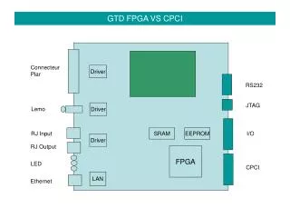
Field Programmable Device • Basic Section of FPD: • Logical Block • Routing (Switch Matrix) • Input Output Block • More Advanced FPD Contains: • On-chip Memory • Embedded Processor • Clock Management • High-Speed Transceiver
FPGA Structures • Basic Lookup Table (LUT)
FPGA Structures • Synchronous Look-UP
FPGA Structures • Routing • Local ( Local connections ) • CLB to CLB • CLB to IOB • Global ( Span all section of chip ) • Global Set/Reset • Global Tri-Sate • Clock
FPGA Structures • Configurable Logic Block (CLB) • Two identical slices in each CLB • Two LUT in each slice • RAM Blocks • Xilinx core generator • Synplify ( Best Synthesizer in the world ) • CLK - Delay Locked Loop (DLL)
CLK - DLL In dealing with a DDR-RAM , CLK-DLL can multiply frequency of CLK by factor 2 , by generating the same signal with 180 degree shift in phase .
Design Flow • Simulation • a) Functional • b) Timing • c) Gate Level
Design Flow • Synthesis • HDL Code to Netlist conversion • Mapping • Digital Circuit Element to Technology Element Mapping • Place & Route • Sitting place for each element of circuit?
Sequential • Basic Sequential Paths: • PAD to clock/Register • Register to Register • Clock/Register to PAD
Translate: ngdbuild • Putting all thing together, so that we need all part of project • Inputs: • Project synthesized EDIF file • UCF constraints file • Core’s .ednfile • Output: Native Generic Database (internal format) • Complete hierarchy .ngdfile
Map • MAP Operation: • Map the generic form to device • Make necessary optimization, eliminate unnecessary logic • Estimate resource usage, just % (110%!) • Check the connection • Input: .ngdfile • Output: .map file
PAR (Place & Route) • PAR Operation: • Place and Route all the logics • Some of placing process done in previous steps • Overused area give error in this section • Input: Unrouted.ncd • Output: Routed.ncd
Recommended Tool Set • Design Entry • HDL Designer / Active HDL / Text Pad • Simulation • ModelSim / Active HDL / NC Sim • Synthesis • XST / Amplify / Synplify • Place & Route • ISE
HDL – Verilog • Verilog Syntax is almost similar to language C , so that learning & understanding of Verilog is very simple . • It’s Module-based like C that is Function-based . For more information on Verilog , look at • Verilog VHDL Golden Reference Guide • Verilog Quick Start