Facility Layout
Facility Layout. Mohamed Iqbal Pallipurath IQSoft. Facility Layout. Facility layout refers to the arrangement of machines, departments, workstations, storage areas, aisles, and common areas within an existing or proposed facility.

Facility Layout
E N D
Presentation Transcript
Facility Layout Mohamed Iqbal Pallipurath IQSoft
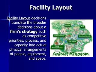
Facility Layout • Facility layout refers to the arrangement of machines, departments, workstations, storage areas, aisles, and common areas within an existing or proposed facility. • Layouts have far-reaching implications for the quality, productivity, and competitiveness of a firm. • Implications: how efficien workers can do their jobs, how fast goods can be produced, how difficult it is to automate a system, and how responsive the system can be to changes in product or service design, product mix, and demand volume.
Objectives of Layout Decision • The basic objective of the layout decision is to ensure a smooth flow of work, material, people, and information through the system. • Minimize material handling costs; • Utilize space efficiently; • Utilize labor efficiently; • Eliminate bottlenecks; • Facilitate communication and interaction between workers, between workers and their supervisors, or between workers and customers; • Reduce manufacturing cycle time and customer service time; • Eliminate wasted or redundant movement; • Facilitate the entry, exit, and placement of material, products, and people; • Incorporate safety and security measures; • Promote product and service quality; • Encourage proper maintenance activities; • Provide a visual control of operations or activities; • Provide flexibility to adapt to changing conditions.
Basic Layouts • Three basic types of layouts: • Process Layout, • Product Layout • Fixed-position Layout • Three hybrid layouts: • Cellular layouts • Flexible manufacturing systems, and • Mixed-model assembly lines
Process Layout • Process layouts, also known as functional layouts, group similar activities together in departments or work centers according to the process or function they perform. • Example, in department store, women's clothes, men's clothes, children's clothes, cosmetics, and shoes are located in separate departments • A process layout is characteristic of intermittent operations, service shops, job shops, or batch production, which serve different customers with different needs. The volume of each customer's order is low, and the sequence of operations required to complete a customer's order can vary considerably
Process Layout (cont’) • Equipment: general purpose, and the workers are skilled at operating the equipment in their particular department. • Advantage: flexibility. • Disadvantage: inefficiency. • Jobs or customers do not flow through the system in an orderly manner, backtracking is common, movement from department to department can take a considerable amount of time, and queues tend to develop. • In addition, each new arrival may require that an operation be set up differently for its particular processing requirements. Although workers can operate a number of machines or perform a number of different tasks in a single department, their workload often fluctuates--from queues of jobs or customers waiting to be processed to idle time between jobs or customers. • See Figure 7.1 (a) and Figure 7.1 (b) for a schematic diagram of process layouts in services and manufacturing.
Process Layout (cont’) • Storage space in a process layout is large to accommodate the large amount of in-process inventory. • The factory may look like a warehouse, with work centers strewn between storage aisles. • In-process inventory is high because material moves from work center to work center in batches waiting to be processed. • Finished goods inventory, on the other hand, is low because the goods are being made for a particular customer and are shipped out to that customer upon completion. • Process layouts in manufacturing firms require flexible material handling equipment (such as forklifts) that can follow multiple paths, move in any direction, and carry large loads of in-process goods. • needs wide aisles to accommodate heavy loads and two-way movement. • Scheduling of forklifts is typically controlled by radio dispatch and varies from day to day and hour to hour. • Routes have to be determined and priorities given to different loads competing for pickup.
Process Layout (cont’) • Process layouts in service firms require large aisles for customers to move back and forth and ample display space to accommodate different customer preferences. • Where to locate the departments or machine centers in relation to each other? • Although each job or customer potentially has a different route through the facility, some paths will be more common than others. • Past information on customer orders and projections of customer orders can be used to develop patterns of flow through the shop.
Product Layouts • Product layouts, better known as assembly lines, arrange activities in a line according to the sequence of operations that need to be performed to assemble a particular product. • Each product or has its own "line" specifically designed to meet its requirements. • The flow of work is orderly and efficient, moving from one workstation to another down the assembly line until a finished product comes off the end of the line. • Product layouts are suitable for mass production or repetitive operations in which demand is stable and volume is high. • The product or service is a standard one made for a general market, not for a particular customer. • High level of demand product layouts are more automated than process layouts, and the role of the worker is different. Workers perform narrowly defined assembly tasks that do not demand as high a wage rate as those of the more versatile workers in a process layout.
Product Layout (cont’) • Advantage: efficient and ease of use. • Disadvantage: Inflexibility. Significant changes in product design may require that a new assembly line be built and new equipment be purchased. • This is what happened to U.S. automakers when demand shifted to smaller cars. • The major concern in a product layout is balancing the assembly line so that no one workstation becomes a bottleneck and holds up the flow of work through the line. • Figure 7.2 shows the product flow in a product layout. Contrast this with the flow of products through the process layout shown in Figure 7.1 (b).
Product Layout (Cont’) • A product layout needs material moved in one direction along the assembly line and always in the same pattern. • Conveyors are the most common material handling equipment for product layouts. Conveyors can be paced (automatically set to control the speed of work) or unpaced (stopped and started by the workers according to their pace). • Assembly work can be performed online (i.e., on the conveyor) or offline (at a workstation serviced by the conveyor). • Aisles are narrow because material is moved only one way, it is not moved very far, and the conveyor is an integral part of the assembly process, usually with workstations on either side. • Scheduling of the conveyors, once they are installed, is simple--the only variable is how fast they should operate.
Product Layout (cont’) • Storage space along an assembly line is quite small • in-process inventory is consumed in the assembly of the product as it moves down the assembly line. • Finished goods, however, may require a separate warehouse for storage before they are shipped to dealers or stores to be sold. • Product and process layouts look different, use different material handling methods, and have different layout concerns. Table 7.1 summarizes the differences between product and process layouts.
Fixed-Position Layouts • Fixed-position layouts are typical of projects in which the product produced is too fragile, bulky, or heavy to move. • Example: Ships, houses, and aircraft are examples. • The product remains stationary for the entire manufacturing cycle. • Equipment, workers, materials, and other resources are brought to the production site. • Equipment utilization is low because it is often less costly to leave equipment idle at a location where it will be needed again in a few days, than to move it back and forth. • Frequently, the equipment is leased or subcontracted, because it is used for limited periods of time. • The workers called to the work site are highly skilled at performing the special tasks they are requested to do. • The wage rate for these workers is much higher than minimum wage. • fixed cost would be relatively low (equipment may not be owned by the company) • variable costs would be high (due to high labor rates and the cost of leasing and moving equipment).
Designing Process Layouts • Objective: minimize material handling costs, which are a function of the amount of material moved times the distance it is moved. • Implication departments that incur the most interdepartment movement should be located closest to each other, and those that do not interact should be located further away. • Techniques: • Block diagramming • Relationship diagramming
Block Diagramming • Step 1: Analyse historical data or predicted movement of material between departments in the existing or proposed facility. • This information is typically provided in the form of a from/to chart, or load summary chart. • The chart gives the average number of unit loads transported between the departments over a given period of time. • A unit load can be a single unit, a pallet of material, a bin of material, or a crate of material--however material is normally moved from location to location. • In automobile manufacturing, a single car represents a unit load. For a ball-bearing producer, a unit load might consist of a bin of 100 or 1,000 ball bearings, depending on their size.
Block Diagramming (cont’) • Step 2: The next step in designing the layout is to calculate the composite movements between departments and rank them from most movement to least movement. • Composite movement, represented by a two-headed arrow, refers to the back-and-forth movement between each pair of departments. • Step 3: Trial layouts are placed on a grid that graphically represents the relative distances between departments in the form of uniform blocks. • The objective is to assign each department to a block on the grid so that nonadjacent loads are minimized. • nonadjacent is defined as a distance farther than the next block, either horizontally, vertically, or diagonally. • The trial layouts are scored on the basis of the number of nonadjacent loads. Ideally, the optimum layout would have zero nonadjacent loads, but in practice it is almost imposible.
Relationship Diagramming • Appropriate for designing process layouts when quantitative data are available. However, in situations for which quantitative data are difficult to obtain or do not adequately address the layout problem, the load summary chart can be replaced with subjective input from analysts or managers. • The thickest lines (three, four, or five strands) identify the closeness ratings with the highest priority--that is, for which departments it is important,especially important, or absolutely necessary that they be located next to each other. • The priority diminishes with line thickness. Undesirable closeness ratings are marked with a zigzagged line. • Visually, the best solution would show short heavy lines and no zigzagged lines (undesirable locations are noted only if they are adjacent). Thin lines (one or two strands, representing unimportant or okay) can be of any length and for that reason are sometimes eliminated from the analysis. • An alternate form of relationship diagramming uses colors instead of line thickness to visualize closeness ratings.
Relationship Diagramming (cont’) • From Figure 7.5(a), it is obvious that production and shipping and receiving are located too far from the stockroom and that the offices and locker room are located too close to one another. • Figure 7.5(b) shows a revised layout, and evaluates the layout with a relationship diagram. The revised layout appears to satisfy the preferences expressed in Muther's grid. The heavy lines are short and within the perimeter of the grid. The lengthy lines are thin, and there are no zigzagged lines.
Computerized Layout Solutions • Several computer packages are available for designing process layouts. The best known is • CRAFT (Computerized Relative Allocation of Facilities Technique) • CRAFT takes a load summary chart and block diagram as input and then makes pairwise exchanges of departments until no improvements in cost or nonadjacency score can be found. The output is a revised block diagram after each iteration for a rectangular-shaped building, which may or may not be optimal. CRAFT is sensitive to the initial block diagram used; that is, different block diagrams as input will result in different layouts as outputs. For this reason, CRAFT is often used to improve upon existing layouts or to enhance the best manual attempts at designing a layout. • CORELAP (Computerized Relationship Layout Planning). • CORELAP uses nonquantitative input and relationship diagramming to produce a feasible layout for up to forty-five departments and different building shapes. It attempts to create an acceptable layout from the beginning by locating department pairs with A ratings first, then those with E ratings, and so on. • Simulation software for layout analysis, such as PROMODEL and EXTEND provide visual feedback and allow the user to quickly test a variety of scenarios. • CAD-integrated layout analysis are available in VisFactory and similar software.
Service Layouts • Most service organizations use process layouts. • Why? • Variability in customer requests for service. • Service layouts are designed in much the same way as process layouts in manufacturing firms, but the objectives may differ. • For example, instead of minimizing the flow of materials through the system, services may seek to minimize the flow of customers or the flow of paperwork. • In retail establishments, the objective is usually related to maximizing profit per unit of display space. • If sales vary directly with customer exposure, then an effective layout would expose the customer to as many goods as possible. This means instead of minimizing a customer's flow, it would be more beneficial to maximize it (to a certain point). • Grocery stores take this approach when they locate milk on one end of the store and bread on the other, forcing the customer to travel through aisles of merchandise that might prompt additional purchases.
Service Layouts • Another aspect of service layout is the allocation of shelf space to various products. • Industry-specific recommendations are available for layout and display decisions. Computerized versions, such as SLIM (Store Labor and Inventory Management) and COSMOS (Computerized Optimization and Simulation Modeling for Operating Supermarkets), consider shelf space, demand rates, profitability, and stockout probabilities in layout design. • Finally, service layouts are often visible to the customer, so they must be aesthetically pleasing as well as functional.
Designing Product Layouts • A product layout arranges machines or workers in a line according to the operations that need to be performed to assemble a particular product. • The layout could be determined simply by following the order of assembly as contained in the bill of material for the product. To some extent, this is true. Precedence requirements specifying which operations must precede others, which can be done concurrently and which must wait until later are an important input to the product layout decision. But there are other factors that make the decision more complicated. • Product layouts or assembly lines are used for high-volume production. • To attain the required output rate as efficiently as possible, jobs are broken down into their smallest indivisible portions, called work elements. • Work elements are so small that they cannot be performed by more than one worker or at more than one workstation. But it is common for one worker to perform several work elements as the product passes through his or her workstation. • Part of the layout decision is concerned with grouping these work elements into workstations so products flow through the assembly line smoothly. • A workstation is any area along the assembly line that requires at least one worker or one machine. • If each workstation on the assembly line takes the same amount of time to perform the work elements that have been assigned, then products will move successively from workstation to workstation with no need for a product to wait or a worker to be idle. • The process of equalizing the amount of work at each workstation is called line balancing.
Line Balancing • Precedence requirements are physical restrictions on the order in which operations are performed on the assembly line. • To facilitate line balancing, precedence requirements are often expressed in the form of a precedence diagram. • The precedence diagram is a network, with work elements represented by circles or nodes and precedence relationships represented by directed line segments connecting the nodes.
Line Balancing (Cont’) • Cycle time, the other restriction on line balancing, refers to the maximum amount of time the product is allowed to spend at each workstation if the targeted production rate is to be reached. • Desired cycle time: • the time available for production / the number of units scheduled to be produced • Cycle time can also be viewed as the time between completed items rolling off the assembly line. Consider the three-station assembly line shown here. • Cycle time can also be viewed as the time between completed items rolling off the assembly line. Consider the three-station assembly line shown here.
Line Balancing (Cont’) • The time required to complete an item is referred to as its flow time, or lead time. • However, the assembly line does not work on only one item at a time. When fully operational, the line will be processing three items at a time, one at each workstation, in various stages of assembly. Every 4 minutes a new item enters the line at workstation 1, an item is passed from workstation 1 to workstation 2, another item is passed from workstation 2 to workstation 3, and a completed item leaves the assembly line. Thus, a completed item rolls off the assembly line every 4 minutes. This 4-minute interval is the actual cycle time of the line. • The actual cycle time, Ca, is the maximum workstation time on the line. • It differs from the desired cycle time when the production quota does not match the maximum output attainable by the system. • Sometimes the production quota cannot be achieved because the time required for one work element is too large. • To correct the situation, the quota can be revised downward or parallel stations can be set up for the bottleneck element.
Line Balancing (Cont’) • Line balancing is basically a trial and error process. • We group elements into work stations recognizing time and precedence constraints. • For simple problems, we can evaluate all feasible groupings of elements. For more complicated problems, we need to know when to stop trying different workstation configurations: The efficiency of the line (E) & theoretical minimum number of workstations (N)
Line Balancing (Cont’) The total idle time of the line, called balance delay, is calculated as (1 - efficiency). Efficiency and balance delay are usually expressed as percentages. In practice, it may be difficult to attain the theoretical number of workstations or 100 percent efficiency.
Line Balancing: Summary • Draw and label a precedence diagram. • Calculate the desired cycle time required for the line. • Calculate the theoretical minimum number of workstations. • Group elements into workstations, recognizing cycle time and precedence constraints. • Calculate the efficiency of the line. • Determine if the theoretical minimum number of workstations or an acceptable efficiency level has been reached. If not, go back to step 4.
Hybrid Layouts • cellular layouts, • flexible manufacturing systems, and • mixed-model assembly lines.
Cellular Layout • Cellular layouts attempt to combine the flexibility of a process layout with the efficiency of a product layout. • Based on the concept of group technology (GT), dissimilar machines are grouped into work centers, called cells, to process parts with similar shapes or processing requirements. (Figure 7.6) • The cells are arranged in relation to each other so that material movement is minimized. Large machines that cannot be split among cells are located near to the cells that use them, that is, at their point of use. • The layout of machines within each cell resembles a small assembly line. Thus, line-balancing procedures, with some adjustment, can be used to arrange the machines within the cell. • The layout between cells is a process layout.
Cellular Layout (Cont’) • Figure 7.7 • Figure 7.8 • Production flow analysis (PFA) is a group technology technique that reorders part routing matrices to identify families of parts with similar processing requirements. • The reordering process can be as simple as listing which parts have four machines in common, then which have three in common, two in common, and the like, or as sophisticated as pattern-recognition algorithms from the field of artificial intelligence. • Figure 7.9 • Figure 7.10 • The U shape of cells 1 and 3 is a popular arrangement for manufacturing cells because it facilitates the rotation of workers among several machines. • Workers in a cellular layout typically operate more than one machine, as was true of the process layout. • However, workers who are assigned to each cell must now be multifunctional--that is, skilled at operating many different kinds of machines, not just one type, as in the process layout. • In addition, workers are assigned a path to follow among the machines that they operate, which may or may not coincide with the path the product follows through the cell.
Advantage of Cellular Layout • Reduced material handling and transit time. • Reduced setup time. • Reduced work-in-process inventory. • Better use of human resources. • Easier to control. • Easier to automate.
Disadvantages of Cellular Layout • Inadequate part families. • Poorly balanced cells. It is more difficult to balance the flow of work through a cell than a single-product assembly line, because items may follow different sequences through the cell that require different machines or processing times. • Expanded training and scheduling of workers. Training workers to do different tasks is expensive and time-consuming and requires the workers' consent. • Increased capital investment. In cellular manufacturing, multiple smaller machines are preferable to single large machines. Implementing a cellular layout can be economical if new machines are being purchased for a new facility, but it can be quite expensive and disruptive in existing production facilities where new layouts are required.
The idea of a flexible manufacturing system (FMS) was proposed in England in the 1960s with System 24 that could operate without human operators 24 hours a day under computer control. The emphasis from the beginning was on automation rather than the reorganization of work flow. Early FMSs were large and complex, consisting of dozens of CNC machines and sophisticated material handling systems. The systems were very automated, very expensive, and controlled by incredibly complex software. The FMS control computer operated the material handling system, maintained the library of CNC programs and downloaded them to the machines, scheduled the FMS, kept track of tool use and maintenance, and reported on the performance of the system. There are not many industries that can afford the investment required for a traditional FMS as described. Fewer than 400 FMSs are in operation around the world today. Currently, the trend in flexible manufacturing is toward smaller versions of the traditional FMS, sometimes called flexible manufacturing cells. It is not unusual in today's terminology for two or more CNC machines to be considered a flexible cell and two or more cells, an FMS. Flexible Manufacturing Systems (FMS)
FMS • FMS layouts differ based on the variety of parts that the system can process, the size of the parts processed, and the average processing time required for part completion. Figure 7.13 and Figure 7.14 show four basic types of FMS layouts: • Progressive layout: All parts follow the same progression through the machining stations. This layout is appropriate for processing a family of parts and is the most similar to an automated group technology cell. • Closed-loop layout: Arranged in the general order of processing for a much larger variety of parts. Parts can easily skip stations or can move around the loop to visit stations in an alternate order. Progressive and closed-loop systems are used for part sizes that are relatively large and that require longer processing times. • Ladder layout: So named because the machine tools appear to be located on the steps of a ladder, allowing two machines to work on one item at a time. Programming the machines may be based on similarity concepts from group technology, but the types of parts processed are not limited to particular part families. Parts can be routed to any machine in any sequence. • Open-field layout: The most complex and flexible FMS layout. It allows material to move among the machine centers in any order and typically includes several support stations such as tool interchange stations, pallet or fixture build stations, inspection stations, and chip/coolant collection systems.
Mixed-Model Assembly Lines • Recognizing that this mismatch of production and demand is a problem, some manufacturers concentrated on devising more sophisticated forecasting techniques. • Others changed the manner in which the assembly line was laid out and operated so that it really became a mixed-model assembly line. • First, they reduced the time needed to change over the line to produce different models. • Then they trained their workers to perform a variety of tasks and allowed them to work at more than one workstation on the line, as needed. • Finally, they changed the way in which the line was arranged and scheduled.
Factors in Designing MMAL • Line balancing: In a mixed-model line, the time to complete a task can vary from model to model. • U-shaped lines. • To compensate for the different work requirements of assembling different models, it is necessary to have a flexible workforce and to arrange the line so that workers can assist one another as needed. Figure 7.15 shows how the efficiency of an assembly line can be improved when a U-shaped line is used. • Flexible workforce. • Although worker paths are predetermined to fit within a set cycle time, the use of average time values in mixed-model lines will produce variations in worker performance. Hence, the lines are not run at a set speed. Items move through the line at the pace of the slowest operation. This is not to say that production quotas are not important. If the desired cycle time is exceeded at any station on the line, other workers are notified by flashing lights or sounding alarms so that they can come to the aid of the troubled station. The assembly line is slowed or stopped until the work at the errant workstation is completed. This flexibility of workers helping other workers makes a tremendous difference in the ability of the line to adapt to the varied length of tasks inherent in a mixed-model line. • Model sequencing. Since different models are produced on the same line, mixed-model scheduling involves an additional decision--the order, or sequence, of models to be run through the line. Another objective in model sequencing is to spread out the production of different models as evenly as possible throughout the time period scheduled. This concept of uniform production will be discussed in Chapter 15, "Just-in-Time Systems."