Facility Layout
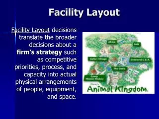
Facility Layout. Cody Comerford Dustin Kovar Michelle Keehan. What is Facility Layout?. Layout decisions entail determining the placement of departments, work groups within the departments, workstations, machines, and stock-holding points within a production facility.

Facility Layout
E N D
Presentation Transcript
Facility Layout Cody Comerford Dustin Kovar Michelle Keehan
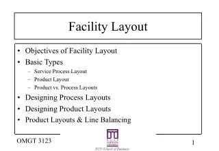
What is Facility Layout? Layout decisions entail determining the placement of departments, work groups within the departments, workstations, machines, and stock-holding points within a production facility. Objectiveis to arrange these elements in a way that ensures a smooth work flow (in a factory) or a particular traffic pattern (in a service organization)
Basic Production Layout Formats • Process • Group similar resources together • Product • Designed to produce a specific product efficiently • Group Technology (Cellular Layout) • Designed to combine aspects of both process and product layouts • Fixed Position • Product is two large to move; e.g. a building
Major Objective of Process Layout: • To MINIMIZE transportation cost, distance, or time • Usually accomplished by locating departments with relatively high interdepartmental work flow as close as possible
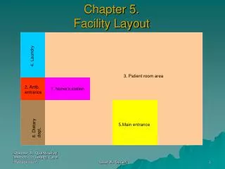
Process Layout • Process Layout Definition: a format in which similar equipment or functions are grouped together (ex. all lathes in one area and all stamping machines in another). A part being worked on then travels, according to the established sequence of operations, from area to area, where the proper machines are located for each operation. • Typical in Hospitals where areas are dedicated to particular types of medical care, such as maternity wards and intensive care units.
Process Layout Also called a job shop or functional layout General purpose & flexible resources Lower capital intensity & automation Higher labor intensity Resources have greater flexibility Processing rates are slower Material handling costs are higher Scheduling resources & work flow is more complex Space requirements are higher
Computerized Layout Techniques - CRAFT Computerized Relative Allocation of Facilities Technique the program calculates the effect on total cost of exchanging departments attempts to minimize materials-handling cost by calculating cost, pair-wise interchanging departments, calculating more costs until a good solution is obtained
Distinguishing features of CRAFT and issues relating: It is a heuristic program. It uses a simple rule of thumb in making evaluations: “Compare two departments at a time and exchange them if it reduces the total cost of the layout.” This type of rule is obviously necessary to analyze even a modest size layout. It does not guarantee an optimal solution. CRAFT is biased by its starting conditions: where you start (that is, the initial layout) will determine the final layout. Starting with a reasonably good solution is more likely to yield a lower-cost final solution, but it does not always. This means that a good strategy for using CRAFT is to generate a variety of different starting layouts to expose the program to different pairwise exchanges.
Distinguishing features of CRAFT and issues relating: It can handle up to 40 departments and rarely exceeds 10 iterations in arriving at a solution. CRAFT departments consist of combinations of square modules (typically representing floor areas 10 feet by 10 feet). This permits multiple departmental configurations, but often results in strange departmental shapes that have to be modified manually to obtain a realistic layout. A modified version called SPACECRAFT has been developed to handle multistory layout problems CRAFT assumes the existence of variable-path material handling equipment such as forklift trucks. Therefore, when computerized fixed-path equipment is employed, CRAFT’s applicability is greatly reduced
Systematic Layout Planning (SLP) Involves developing a relationship chart showing the degree of importance of having each department located adjacent to every other department From this chart, an activity relationship diagram, similar to the flow graph used for illustrating material handling between departments, is developed The SLP approach has been quantified for ease of evaluating alternative layouts
Assembly Lines • Progressive assembly linked by some material handling device • Different line types • Material handling devices • Line configuration • Pacing • Product Mix • Workstation characteristics • Length • Range of Products
I Love Lucy Overstates the pressure of assembly-line work http://www.youtube.com/watch?v=4wp3m1vg06Q
Assembly Line Balancing • Workstation Cycle Time • Time between successive units coming off the end of the line • Tasks • Elements • Work Units • The total work to be performed at each workstation is equal to the sum of the tasks assigned to the workstation.
Assembly Line Balancing • Problem: • each workstation has no more than can be done in the workstation cycle time • Precedence Relationship • Specifies the order in which tasks must be performed in the assembly process
Step 3Determine theoretical minimum number of workstations required to satisfy the workstation cycle time constraint
Step 4 Select a primary rule by which tasks are to be assigned to workstations and a secondary rule to break ties.
Step 5Assign tasks to the first workstation until the sum of the task times is equal to the workstation cycle time, or no other tasks are feasible because of time or sequence restrictions. Repeat for other workstations.
Step7If efficiency is unsatisfactory, rebalance using a different decision rule
Splitting Tasks Split the task Share the task Use parallel workstations Use a more skilled worker Work overtime Redesign
Line Layouts Unequal workstation times can be solved through line layout: Flexible Line Layouts U-shaped line layouts
Mixed-Model Line Balancing • Objective • Meet demand for a variety of products and to avoid building high inventories • Steps • Schedule different models to be produced over a given day or week on the same line in a cyclical fashion.
Overview • Intentions • Incorporate greater flexibility in products produced on the line • More variability in workstations • Improve reliability • High quality output
Comparison of Product vs. Product Layouts Process Layouts Product Layouts Products:large #, different small # efficiently Resources:general purpose specialized Facilities: more labor intensive more capital intensive Flexibility:greater relative to market lower relative to market Processing slower faster Rates: Handling costs:high low Space requirements:higher lower
SimQuick Example 19
GT Layout • Group Technology (GT) layout allocates dissimilar machines into cells to work on products that have similar shapes and processing requirements. • Also known as cellular layout. • Widely used in: • Metal fabricating • Computer chip manufacturing • Assembly work
GT Layout • Overall objective is to gain benefits of product layout in job-shop kinds of production. • Benefits include: • Better human relations • Cells consist of few workers who for a small work team, and the team turns out completed units of work. • Improved operator expertise • Workers see only a limited number of different parts in a finite production cycle, so repetition means quick learning.
GT Layout • Benefits cont. : • Less in-process inventory and material handling • A cell combines several production stages, so fewer parts travel through the shop. • Faster production setup • Fewer jobs mean reduced tooling and hence faster tooling changes.
Developing a GT Layout Grouping parts into families that follow a common sequence of steps. This step requires developing and maintaining a computerized parts classification and coding system. Identifying dominant flow patterns of parts families as a basis for location or relocation of processes. Physically grouping machines and processes into cells. Often there will be parts that cannot be associated with a family and specialized machinery that cannot be placed in any one cell due to its general use.
GT Layout Parts that undergo similar processes, are put together into cells.
GT Layout Process flow before GT cells.
GT Layout Process flow after the use of GT cells.
Fixed Position Layout • Fixed-position layout is characterized by a relatively low number of production units in comparison with process and product layout formats. • Mainly used for products that are too large or heavy to move. • Example: • Construction (buildings, dams, power plants) • Shipbuilding, aircraft, aerospace • Oil drilling, home repair, farms
Fixed Position Layouts • In order to make this work, required resources must be portable so they can be taken to the job for “on the spot” performance. • Due to the nature of the product, the user has little choice in the use of fixed position layout. • Disadvantages: • Space • The work area may be crowded so that little storage space is available. Can cause material handling problems. • Administration • Administration burden is higher. Span of control can be narrow, and coordination difficult.
Retail Service Layout • Objective of retail service layout is to maximize net profit per square foot of store space. • Found in: • Stores • Banks • Restaurants
Retail Service Layout • Taco Bell Restaurants have been very successful in leveraging every inch of its layout space to maximize net profit. • Key operational modifications include: • Elimination of many on-site food preparation steps. • Which simultaneously increased the speed of service while reducing the amount of working space needed.
Retail Service Layout Taco Bell Restaurant Floor Plans
Retail Service Layout • Servicescapes • Refers to the physical surroundings in which the service takes place and how these surroundings affect customers and employees. • Ambient Conditions • Refers to the background characteristics such as noise level, music, lighting, temperature, and scent that can affect employee performance and morale as well customers’ perceptions of the service.
Retail Service Layout • Spatial Layout and Functionality • Two important aspects: • Circulation path of customers • Grouping the merchandise
Office Layout The trend in office layout is toward more open offices, with personal work spaces separated only by low divider walls. Companies have removed fixed walls to foster greater communication and teamwork.
Office Layout • Office Layout Considerations: • Almost half of US workforce works in an office environment • Human interaction and communication are the primary factors in designing office layouts • Layouts need to account for physical environment and psychological needs of the organization • Open concept offices promote understanding & trust • Flexible layouts incorporating “office landscaping” help to solve the privacy issue in open office environments
Homework Assignment • SimQuick • Exercise 19- Page 73 • Exercise 20- Page 75