Download
1 / 27
320 likes | 661 Vues
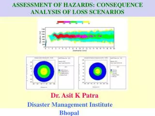
ASSESSMENT OF HAZARDS: CONSEQUENCE ANALYSIS OF LOSS SCENARIOS. Dr. Asit K Patra Disaster Management Institute Bhopal. Logic Diagram for Consequence /Risk Analysis. Release of Hazardous Substance. Discharge & Dispersion Models. Flammable Release. Toxic Release.

E N D
ASSESSMENT OF HAZARDS: CONSEQUENCE ANALYSIS OF LOSS SCENARIOS Dr. Asit K Patra Disaster Management Institute Bhopal
Logic Diagramfor Consequence /Risk Analysis Release of Hazardous Substance Discharge & Dispersion Models Flammable Release Toxic Release Explosion & Fire Models Consequence Models Mitigation Factors Risk Calculation
Components of Consequence Analysis 1. Discharge Models : Loss of containment/Release scenarios.2. Dispersion Models : Transport and dispersion of released flammable/Explosive/toxic chemicals.3. Consequence/Effect models: Effect on people, property and environment.
Typical Release Scenarios Liquid Discharges* Hole in atmospheric storage tank or other atmospheric storage vessel or pipe under liquid head.* Hole in vessel or pipe containing pressurized liquid below its normal boiling point. Gas Discharges* Hole in equipment (pipe, vessel) containing gas under pressure * Relief valve discharge (of vapour only) Contd..
Typical Release Scenarios *Evaporation from liquid pool (e.g., naptha, heavy cut etc.)*Relief valve discharge from top of pressurized storage tank * Generation of toxic combustion products as a result of fire (C) Two-Phase Discharges* Hole in pressurized storage tank or pipe containing a liquid above its normal boiling point.
Scenario Identification Pressure Relief Devices Relieving Directly to the Atmosphere:
Scenario Identification Vessels : Rupture based on largest diameter process pipe attached to the vessel
Scenario Identification Tank Overflows and Spills
……. …….. ……… …. .. . TBOILING POINT < T AMBIENT Leak Tank with liquid Flash Aerosol Boiling Pool ++++++++++++++++ +++++++++++++++++++++++ ++++++++++++++++ Pool Spread Example: Super-heated release (Release of LPG/Liquid Chlorine)
Immediate ignition Jet fire Ignition Open atmosphere Flash fire Delayed ignition Congested atmosphere Vapour cloud explosion Release No ignition Safe dispersion EXAMPLE – RELEASE OF PRESSURISED GAS
Immediate ignition Pool fire Ignition Open atmosphere Flash fire Delayed ignition Congested atmosphere Vapour cloud explosion Release No ignition Safe dispersion EXAMPLE – RELEASE OF A REFRIGERATED LIQUEFIED GAS
No cooling BLEVE Immediate ignition Cooling Ignition Jet fire Open atmosphere Flash fire Delayed ignition Release Congested atmosphere VCE No ignition Safe dispersion EXAMPLE – EVENT TREE FOR RELEASING OF LIQUEFIED GAS UNDER PRESSURE
Consequence Analysis using PHAST RISK Scenario: Jet Fire Scenario of Natural Gas while being transported through pipelinePipe Diameter: 20 inches Pipe Length: 10 KmPipe Press: 500 psia Pipe Temperature: 35° CWind: 5 meters/second Ground Roughness: Industrial Air Temperature: 35° C Stability Class: DRelative Humidity: 70% *******************************************************THREAT ZONE: Threat Modeled: Thermal radiation from jet fire4.5 Kw/m2 (Blue Zone) 168 12.5 Kw/m2 (Orange Zone) 9937.5 Kw/m2 (Red Zone)45 meters
Consequence Analysis using PHAST RISK Scenario:Catastrophic rupture of a Naptha storage tank: Pool FireChemical details :* Capacity of tank = 950 m3. * Density at 20OC = 0.93 g/ml.* Dyke Dimension: 40.5 m x 36.25 m* Storage Conditions: Atmospheric.* LFL/LEL = 1% by volume of air.Table 1 : Maximum affected distances (in meter) for Pool fire scenarios under D class with wind speed of 5.0 m/s Thermal radiation Affected Distance in Metre from Pool levels for Fire 4.5 Kw/m2 (Blue Zone) 69 12.5 Kw/m2 (Orange Zone) 2437.5 Kw/m2 (Red Zone) Not Reached
Factors Affecting Transport and Dispersal of toxic chemicals Wind speed & direction :Dilutes the released chemical and then it spreads along the wind direction. Thermal stability : Stable (E - F), Neutral(D) and Unstable (A-C) Temperature Inversion : Suppress the movement of toxic cloud.
Stability Class(Pasquill, 1961).(i) A Class : Very Unstable. Imagine summernoon time.(ii) B Class : Unstable. (iii) C Class : Slightly Unstable. (iv) D Class : Neutral. Slightly cloudy. (v) E Class : Stable.(vi) F Class : Very stable. Imagine Winter Night.
Contd.Scenario:Release of Chlorine from a tonner through hole with various sizes (Inventory = 900 Kg).Table 1 : Maximum Downwind Effect Distance (km) of Chlorine Vapour Cloud under various atmospheric conditionsHole Diameter Atmospheric Stability Class and Wind Speed (mm) F ; 1.5 m/s D; 3.0 m/s A; 2 m/s 5.0 0.77 0.20 0.05*10.0 1.61 0.44 0.11 *15.0 2.70 0.71 0.15 20.0 3.65 0.95 0.23
Consequence Analysis using Phast Risk Scenario:Catastrophic Failure of a Chlorine Tonner (Contains 900 kg)ConcentrationMaximum Downwind Distance (m) (ppm) under the following atmospheric conditions B ; 2.0 m/s D; 4.0 m/s F; 1.5 m/s 1000 (Fatal) 206 286 195 35 668 1432 2957 10 (IDLH) 1208 2858 7516 3 (STEL) 2109 5350 16260
Dispersion Modelling of Chlorine gas after being released from CWPH in NTPC, Singorli Inventory = 900 kg.)
Outcome of Consequence Analysis(a) Maximum loss scenarios(b) Consequences in terms of Heat radiation, Over pressure and intoxication.(c) Identification of vulnerable zones and classification of units which have the potential for creating an off-site emergency. (d)Identification of important facilities which are coming into the vulnerable zones.(e) Selection of assembly point/escape route/Adm. Building etc.
Infrastructures required for Consequence/Risk Analysis DMI . Complete Inventory of hazardous processes, chemicals, details of storage (T, P, type of vessel etc.) etc. . Expert professionals having thorough understanding of the process thermodynamics and atmospheric dispersion.. Meteorological data and knowledge of stability classes.. Relevant Software to predict vulnerable zones
For Further Information, Please contact:asitbangra@rediffmail.com Thanks