Keyboard Level Model (KLM): Practical Design Tool for Task Efficiency
440 likes | 472 Vues
Understand how KLM captures and calculates user actions for task completion. Explore the operators and encoding methods to predict task execution time by expert users. Discover applications in user interaction modeling.

Keyboard Level Model (KLM): Practical Design Tool for Task Efficiency
E N D
Presentation Transcript
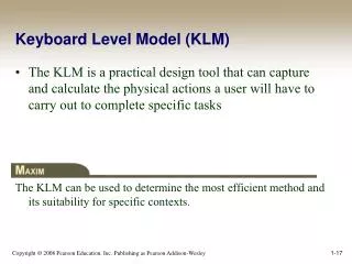
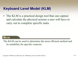
Keyboard Level Model (KLM) • The KLM is a practical design tool that can capture and calculate the physical actions a user will have to carry out to complete specific tasks The KLM can be used to determine the most efficient method and its suitability for specific contexts.
Keyboard Level Model (KLM) • Given: • A task (possibly involving several subtasks) • The command language of a system • The motor skill parameter of the user • The response time parameters • Predict: The time an expert user will take to execute the task using the system • Provided that he or she uses the method without error
Keyboard Level Model (KLM) • The KLM is comprised of: • Operators • Encoding methods • Heuristics for the placement of mental (M) operators
KLM - Operators • Operators • K Press a key or button • P Point with mouse • H Home hands to keyboard or peripheral device • D Draw line segments • M Mental preparation • R System response • KLM of Type a transform in Goblinxna, and then compile
KLM – Encoding Methods • Encoding methods define how the operators involved in a task are to be written MK[i] K[p] K[c] K[o] K[n] K[f] K[i] K[g] K[RETURN] It would be encoded in the short-hand version as M 8K [ipconfig RETURN] This results in a timing of 1.35 + 8 * 0.20 = 2.95 seconds for an average skilled typist.
KLM – Heuristics for M Operator Placement • The KLM operators can be placed into one of two groups—physical or cognitive. • The physical operators are defined by the chosen method of operation, such as clicking an icon or entering a command string. • The cognitive operators are governed by the set of heuristics
What the KLM Does Not Do • The KLM was not designed to consider the following: • Errors • Learning • Functionality • Recall • Concentration • Fatigue • Acceptability
Applications for the KLM • Case 1 (Mouse-Driven Text Editor) • During the development of the Xerox Star KLMs served as expert proxies • Case 2 (Directory Assistance Workstation) • The KLM clarified the tradeoffs between the number of keystrokes entered in the query and the number of returned fields
GOMS Goal/task models can be used to explore the methods people use to accomplish their goals • Card et al. suggested that user interaction could be described by defining the sequential actions a person undertakes to accomplish a task. • The GOMS model has four components: • goals • operators • methods • selection rules
GOMS • Goals - Tasks are deconstructed as a set of goals and subgoals. • Operators - Tasks can only be carried out by undertaking specific actions. • Methods - Represent ways of achieving a goal • Comprised of operators that facilitate method completion • Selection Rules - The method that the user chooses is determined by selection rules
GOMS – CMN-GOMS CMN-GOMS can predict behavior and assess memory requirements • CMN-GOMS (named after Card, Moran, and Newell) -a detailed expansion of the general GOMS model • Includes specific analysis procedures and notation descriptions • Can judge memory requirements (the depth of the nested goal structures) • Provides insight into user performance measures
GOMS – Other GOMS Models • NGOMSL (Natural GOMS Language), developed by Kieras, provides a structured natural-language notation for GOMS analysis and describes the procedures for accomplishing that analysis (Kieras, 1997) • NGOMSL Provides: • A method for measuring the time it will take to learn specific method of operation • A way to determine the consistency of a design’s methods of operation
GOMS – Other GOMS Models • CPM-GOMS represents • Cognitive • Perceptual • Motor operators • CPM-GOMS uses Program Evaluation Review Technique (PERT) charts • Maps task durations using the critical path method (CPM). • CPM-GOMS is based directly on the Model Human Processor • Assumes that perceptual, cognitive, and motor processors function in parallel
GOMS – Other GOMS Models • Program Evaluation Review Technique (PERT) chart Resource Flows
Modeling Structure • Structural models can help us to see the relationship between the conceptual components of a design and the physical components of the system, allowing us to judge the design’s relative effectiveness.
Modeling Structure – Hicks Law Hick’s law can be used to create menu structures • Hick’s law states that the time it takes to choose one item from n alternatives is proportional to the logarithm (base 2) of the number of choices, plus 1. • This equation is predicated on all items having an equal probability of being chosen
Modeling Structure – Hicks Law T = a +b log2(n 1) • The coefficients are empirically determined from experimental design • Raskin (2000) suggests that a 50 and b 150 are sufficient place holders for “back-of-the-envelope” approximations
Modeling Structure – Hicks Law Menu listing order must be logical and relevant • Menus are lists grouped according to some predetermined system • If the rules are not understood or if they are not relevant to a particular task, their arrangement may seem arbitrary and random, requiring users to search in a linear, sequential manner.
Modeling Dynamics Understanding the temporal aspects of interaction design is essential to the design of usable and useful systems • Interaction designs involve dynamic feedback loops between the user and the system • User actions alter the state of the system, which in turn influences the user’s subsequent actions • Interaction designers need tools to explore how a system undergoes transitions from one state to the next
Modeling Dynamics – State Transition Networks • State Transition Networks can be used to explore: • Menus • Icons • Tools • State Transition Networks can show the operation of peripheral devices
Modeling Dynamics – State Transition Networks • State Transition Network • STNs are appropriate for showing sequential operations that may involve choice on the part of the user, as well as for expressing iteration.
Modeling Dynamics – Three-State Model The Three-State Model can help designers to determine appropriate I/O devices for specific interaction designs • The TSM can reveal intrinsic device states and their subsequent transitions • The interaction designer can use these to make determinations about the correlation between task and device • Certain devices can be ruled out early in the design process if they do not possess the appropriate states for the specified task
Modeling Dynamics – Three-State Model • The Three-State Model (TSM) is capable of describing three different types of pointer movements • Tracked: A mouse device is tracked by the system and represented by the cursor position • Dragged: A mouse also can be used to manipulate screen elements using drag-and-drop operations • Disengaged movement: Some pointing devices can be moved without being tracked by the system, such as light pens or fingers on a touchscreen, and then reengage the system at random screen locations
Mouse Three-State Model. Trackpad Three-State Model. Alternate mouse Three-State Model. Multibutton pointing device Three-State Model. Modeling Dynamics – Three-State Model
Modeling Dynamics – Glimpse Model • Forlines et al. (2005): • Because the pen and finger give clear feedback about their location when they touch the screen and enter state 2, it is redundant for the cursor to track this movement • Pressure-sensitive devices can take advantage of the s1 redundancy and map pressure to other features • Undo commands coupled with a preview function (Glimpse) can be mapped to a pressure-sensitive direct input device
Modeling Dynamics – Glimpse Model • Some applications • Pan and zoom interfaces—Preview different magnification levels • Navigation in a 3D world—Quick inspection of an object from different perspectives • Color selection in a paint program—Preview the effects of color manipulation • Volume control—Preview different volume levels • Window control—Moving or resizing windows to view occluded objects • Scrollbar manipulation—Preview other sections of a document
Physical Models • Physical models can predict efficiency based on the physical aspects of a design • They calculate the time it takes to perform actions such as targeting a screen object and clicking on it
Example • Five fastest places to click on for a right-handed user?
Physical Models – Fitts’ Law • Fitts’ law states that the time it takes to hit a target is a function of the size of the target and the distance to that target Fitts’ law can be used to determine the size and location of a screen object
Physical Models – Fitts’ Law • There are essentially three parts to Fitts’ law: • Index of Difficulty (ID)—Quantifies the difficulty of a task based on width and distance • Movement Time (MT)—Quantifies the time it takes to complete a task based on the difficulty of the task (ID) and two empirically derived coefficients that are sensitive to the specific experimental conditions • Index of Performance (IP) [also called throughput (TP)]—Based on the relationship between the time it takes to perform a task and the relative difficulty of the task
Physical Models – Fitts’ Law • Fitts described “reciprocal tapping” • Subjects were asked to tap back and forth on two 6-inch-tall plates with width W of 2, 1, 0.5, and 0.25 inches
Physical Models – Fitts’ Law • Fitts proposed that ID, the difficulty of the movement task, could be quantified by the equation ID = log2(2A/W) Where: A is the amplitude (distance to the target) W is the width of the target • This equation was later refined by MacKenzie: ID = log2(A/W + 1)
Physical Models – Fitts’ Law • The average time for the completion of any given movement task can be calculated by the following equation: MT = a +b log2(A/W + 1) Where: MT is the movement time Constants a and b are arrived at by linear regression
Physical Models – Fitts’ Law • By calculating the MT and ID, we have the ability to construct a model that can determine the information capacity of the human motor system for a given task. • Fitts referred to this as the index of performance (throughput) • Throughput is the rate of human information processing TP = ID/MT
Physical Models – Fitts’ Law • Implications of Fitts’ Law • Large targets and small distances between targets are advantageous • Screen elements should occupy as much of the available screen space as possible • The largest Fitts-based pixel is the one under the cursor • Screen elements should take advantage of the screen edge whenever possible • Large menus like pie menus are easier to uses than other types of menus.
Physical Models – Fitts’ Law • Limitations of Fitts’ Law • There is no consistent way to deal with errors • It only models continuous movements • It is not suitable for all input devices, for example, isometric joysticks • It does not address two-handed operation • It does not address the difference between flexor and extensor movements • It does not address cognitive functions such as the mental operators in the KLM model
Physical Models – Fitts’ Law • W is computed on the same axis as A Horizontal and vertical trajectories Targeting a circular object.
Physical Models – Fitts’ Law • Bivariate data • Smaller-Of—The smaller of the width and height measurements: IDmin(W, H ) = log2 [D/min (W, H ) + 1] This is not a particularly good method. Why?
Physical Models – Fitts’ Law • Amplitude Pointing: One-dimensional tasks • Only the target width (whether horizontal or vertical) is considered • The constraint is based on W, and target height (H) is infinite or equal to W • AP errors are controlled at “the final landing” • Directional Pointing: If W is set at infinity then H becomes significant • The constraint is based on H • DP errors are corrected incrementally during the pointing movement (Accot & Zhai, 2003)
Physical Models – Fitts’ Law • Implications for interaction design: • Overly elongated objects hold no advantage (W/H ratios of 3 and higher). • Objects should be elongated along the most common trajectory path (widgets normally approached from the side should use W, those approached from the bottom or top should use H). • Objects should not be offset from the screen edge (consistent with the Macintosh OS). • Objects that are defined by English words generally have W>H and should be placed on the sides of the screen. (However, greater amplitude measurements may be significant on the normal “landscape”-oriented screens.) (Accot & Zhai, 2003)