Structural Collapse Technician Training-Ver. 3.1
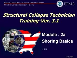
Structural Collapse Technician Training-Ver. 3.1. Module : 2a Shoring Basics Jul12 . Terminal Objectives. The Student shall understand the function & capacity of the Shoring used in US&R to support damaged structures

Structural Collapse Technician Training-Ver. 3.1
E N D
Presentation Transcript
Structural Collapse Technician Training-Ver. 3.1 Module : 2a Shoring Basics Jul12
Terminal Objectives • The Student shall understand the function & capacity of the Shoring used in US&R to support damaged structures • The Student should also understand why and how these Shores are constructed Basic Definition Shoring for US&R is the TEMPORARY Support of Only That Part of a Damaged Structure that is REQUIRED for Conducting Operations at REDUCED RISK
Key Learning Points - 1 • What is Size and Type of Load that needs to be supported? • The weight of the supporting structure plus its overload, or just its overload • Broken Structure or Rigid Structure • How much Shoring do you need? • Should Shoring be similar to a Life Jacket? – providing just enough lift to keep one afloat • Some portion of the load can be (is being) carried by the un-shored structure
Key Learning Points - 2 • What is the Capacity for the various types of US&R Shoring Systems? • How to configure US&R Shoring to ensure a predictable & slow Failure Mode • How to sequence the construction of US&R shoring in order to Minimize Risk • What are initial, short-term systems • What are more long-term systems • What are Class 1, 2, & 3 Systems • What is sequence in Multi-Story Shoring? • How and When to Inspect US&R Shoring
USACE FOG & SOG • Sect 1 • Haz ID + Marking Sys • Sect 2 • Vert Shoring • Sect 3 • Lateral Shoring • Sect 4 • Repair Techniques • FAQ & Glossary • SOG has added Eng Tables • Sect 5 • Equip Ops Procedures • Sect 6 • Reference Data • Sect 7 • Engineering Tables • Sect 8 • USACE StS Deployment Ck-Lists • Sect 9 • FEMA StS Deployment Ck-Lists & Forms Sect 1-9 Sect 1-4
Collect Load Distribute Load Double Funnel Principle • Need Posts / Shores with Adjustability & Positive Connections • Need Lateral Bracing • Need System with Forgiveness
Weights of Building Materials • Reinforced concrete = 150 pcf • Concrete columns & beams weigh more (16"sq w/ 5% rebar = 170pcf) • Masonry = 125 pcf • Wood = 35 pcf (dry) • Steel = 490 pcf • Concrete or masonry rubble = 10 psf per inch
Quick way to estimate weightsBase estimate on approximate weight per square foot for unit thickness of concrete (12") and steel (1") • 12" conc slab = 150 psf • 10' conc slab = 125psf • 8" conc slab = 100psf • 6" conc slab = 75psf (and so on) • 1" steel plate = 40psf • ¾" steel pl = 30psf • ½" steel pl = 20psf • ¼" steel pl = 10psf (and so on)
Weights of Building Construction • Concrete floors = 90 to 150 psf • Light weight concrete is about 80% • Steel systems w/ conc fill slabs = 50 to 70 psf • Wood floor = 10 to 25 psf • (post 1960 wood floors may have concrete fill) • Add 10 to 15 psf for wood/metal interior walls • each floor • Add 10 psf or more each floor or furniture etc. • More for storage • Add 10 psf or more for Rescuers
Example • Assume that this 20ft x 30ft classroom has an 8" thick concrete roof with 6" of debris on it WHAT IS THE TOTAL LOAD TO SHORE ? 8" concrete = 100 psf x 20 x 30 = 60,000 lb 6" debris = 60 psf x 20 x 30 = 36,000 lb Lights, ducts, ceiling, etc. = 5 psf = 3,000 lb Rescuers = 10 psf x 20 x 30 = 6,000 lb* TOTAL (105 Kips) = 105,000 lb * 6,000 lb Rescuers allows for 24 - 250 lb FF Is this reasonable ? • If not use more, this is a MINIMUM
Shoring in Multi-story Structures • For Existing, "Sound" Buildings - Only • Wood Building: one undamaged floor can support one damaged floor • Steel Building: 2 undamaged for 1 damaged • Reinforced Concrete: 3 for 1 • Precast Concrete: start at ground • Assumptions • "Normal" loading - no heavy debris, etc • Not for buildings under construction • See Manual & Input from StS • Not for any buildings that collapse unexpectedly – w/o Quake, Blast, etc
Shoring in Multi-story Structures – cont. • Sequence for multi-story Shoring – Where do you start? • Start directly under lowest "Damaged" or "Overloaded" Floor in order to share the load • Keep shoring in all stories vertically aligned • Other Strategies • Shore from Outside - In • Shore for Team Access & Egress • Phased approach – see next slide • Spot shore - Class 1 • 2 Dimensional - Class 2 • 3 Dimensional - Class 3
Class 1 – Class 2 – Class 3 T Shore – 2 Post Vertical – Laced Post
Shoring Selection Considerations • Condition of damaged floor / wall • Solid with cracks • Badly cracked concrete or masonry • Wood joist - Wood truss • Steel beam - Steel bar joist • PC Concrete - T, Dbl T, I-Beam, Slab (hollow sections)
Shoring Selection Considerations • Condition of supporting surface • Solid ground - slab on ground • Rubble covered ground or slab • Undamaged floors in multi-story bldg • Basement - but now many floors below • Availability of shoring materials & local contractors
Shoring Selection Considerations • Damaged buildings often contain vertical as well as lateral instabilities • Uncollapsed building have been 10% out of plumb in one story (requires lateral shoring to support 10% of total weight of building + aftershock) • StS needs to design
Building Out of Plumb Forces 100K 10K 10ft 1 1ft
Shoring Selection Considerations • Collapses with large pieces may have unseen interdependencies • Sloped floors & walls are difficult. • Loads are vertical due to gravity • Contact surfaces are sloped and lateral forces need to be considered and resisted.
Needs for Shoring Systems • Easy to calculate Total Load of structure • Don't know where load is concentrated • Similar to mine collapse - unknown load distribution • Shoring system must give warning of overload • Need recognizable "Structural Fuses" • Brittle failure mode is highly undesirable • Avoid systems that have Buckling Failure
Use Unique Property of Timber To Provide Warning of Overload • Growth pattern of tree • Rapid growth in spring deposits relatively soft fiber • Slower growth rate in summer deposits more dense fiber • If load end grain, crushing strength is determined by summerwood • If load is on side (cross-grain), soft springwood determines strength • Cross-grain bearing failure is slow and noisy - (gives warning)
Capacity Of Wood Posts • Slenderness (L/D) determines the buckling strength of a wood post (L/D = length/width) • Buckling failure is sudden and undesirable • The maximum allowable L/D is 50 • For better failure mode posts should be constructed so their L/D is less than 25 • This will insure that cross-grain crushing can occur and be observed at a load that is lower than the Buckling Load.
Capacity of Wood Posts • For L/D to be 25 or Less • 4 x 4 should be kept shorter than 8 feet • 6 x 6 should be kept shorter than 12 feet • This is not always possible • If a post is properly braced at its mid-height, its Effective length is half its Total length. • Bracing must be placed in N-S as well as E-W direction and properly nailed • FEMA, US&R shoring has lots of bracing
Cribbing Steel Pipe Metal Frames & Joist Pneumatic Shores Shores for Sloped Surfaces Vertical Shoring Systems • Wood Posts • Ellis Clamps & Jacks • T - Spot Shore • Window / Door • Laced Posts • Ply Laced Posts
Header Sole Plate Post Wall Plate Raker Raker Cleat Gussets Diagbrac'g Ply Braces Collects load at roof and floor Transmits load to floor or ground 4x4 or 6x6 from header to sole Collects load from wall/vert. surface 4x4 or 6x6 from wall plate to sole 18" to 30" 2x connection pieces 5/8 or 3/4 Ply (or OSB) connections ( 12"x12" full, 6"x12" half, 12"x24" double) 2x4, 6 as X or V between shores 8" & 24" wide ply horiz. braces at PLP US&R Shoring Terminology
Vertical Wood Shore – Class 2 • Plywood half-gussets to post, 1 side at top with 4x4 & 6x6 header (Dbl gusset + add on opp. side of diag brace at bottom) • 2x6 diag braces • 1x6 brace for 4x4 > 8'(3/4" x 6" ply is alternative) • Full width wedges w/ keeper nails. • Nail 2x6 diag. brace w/5-16d to sole, header, & each post (may use 3-16d to post at bottom)
Load Path - Vertical Load Load Resistance
Load Load Everything reverses when Load comes from the Left Load Path - Lateral Load Resistance Resistance
Vertical Shore - Important Joints header • 2x6 diagonal needs to be carefully positioned • To provide a competent load path • To fit 5-16d to header, post & sole • May use 3-16d to post at bottom • To confine wedges and reduce roll over at bottom • For most long-incidents, need to add gusset on opposite side of diagonal brace to protect against sole roll-over & wedge pop-out post sole
Design Load H = Height Each Post 8' - 0" 8,000# * 10' - 0" 5,000# 12' - 0" 3,500# Vertical Wood Shores4x4 Posts System with 4x4 Sole Header Size Use 4x4 min. if posts are placed directly under floor beams or when supporting intact/rigid concrete slab or beam. See Structures Spec for other conditions * = based on 660 psi cross-grain bearing
Vertical Wood Shores6x6 Post System with 6x6 Sole Header Size Use 6x6 min. if posts are placed directly under floor beams or when supporting intact/rigid concrete slab or beam. See Structures Spec for other conditions. H = Design Load Height Each Post 12' - 0" 20,000# * 14' - 0" 14,500# 16' - 0" 12,000# 18' - 0" 9,000# 20' - 0" 7,500# * = based on 660 psi cross-grain bearing
Assumptions - Vertical Shore • Configurations show Post Design Load for given heights • The 4x4 and 6x6 Header Size assumes: • Posts are 4 ft max o.c. • Post are aligned with floor beams • Or that supported concrete is rigid enough to span between posts • If not the case - StS must design header • Max. slope of floor/header is 5% (6" in 10')
Properties Of Good Wood • Minimum of 8 Rings per Inch • Slope of Grain = 8 to 1 or Less • Maximum Tight Knot = 1 1/2 in. • Maximum Loose Knot = 3/4 in. • If Doug Fir or Southern Pine have this type of grain, Factor of Safety = 2 ?
Vertical ShoreShort Term & Light Load For Light Frame where no displacement due to lateral loads, vibration or load shifting is likely
Vertical Shore – Fully connected systemGussets each side at sole to restrain wedges
2-Post Vertical Wood Shores • Plywood half-gussets ea. side each post, except at diagonal (gussets only one side for 4x4, 6x6 Header) • 2x4 diagonal brace w/3-16d ea end & to posts (7'-6" max long to resist tension/compression) • 2x4 mid brace • 4x4 Posts at 4' max. o.c. (5'max. o.c. at 6x6) • 2x wedges w/ toenails Same as One Face of Laced Post Shore
2 Post Vertical ShoreBuilt during training(Diagonals may be in any configuration, K or parallel)
2 Post Vertical Shore - Limited Height • Plywood half-gussets ea. side each post, except at diagonal (gussets only one side for 4x4, 6x6 Header) • 2x6 diagonal brace w/5-16d to sole, header & to post (7'-6" max long to resist tension & compression) • 4x4 Posts at 4' max. o.c. (5' max. o.c. at 6x6) • Full width 2x wedges w/ keeper nails. 6' Max. Height of Shore
880 Freeway using 12x12& Steel W as sole, no connections or bracing Vertical Shores
Vertical Shores - 880 Freeway Using 12xshores & sole, no connections & bracing
Ellis Shores - 4x4 adjustable • Need 2 Ellis Clamps to make a pair of 4x4 into Adjustable 4x4 shore • Need Ellis Jack • Failure Mode is by clamp crushing the side grain of the post - Gives Warning • Design Load = 6000 lb • Not in current cache 6" 12" 6" 12-0 max 7-0 max
Screw Jack by Ellis • Adjustable metal foot for 4x4 and 6x6 wood posts • 6 inch adjustment - set half way to get 3 in. up & down • Metal Foot is stronger than wood post • Use sole to spread load
Ellis Foot was used in Half Mile TunnelUnder Kansas Grain Elevator that Exploded Closure doors were blown off the bottoms of cylinders & grain filled the tunnel
Ellis foot used to develop friction conn.To support new closures Plywood closures stopped the grain flow so tunnel could be emptied using a large vacuum
T - Spot Shore – Class 1 Full Gusset Temporary Shore Basically Unstable Typical header is 3 ft and centered on Load Dbl T is more stable 11 ft Max Height (10'-3" Post) Post strength is Limited by stability 2 ft to 3 ft sole plate, same size as header Design Load = 1k? Half Gusset
The Dbl "T" Shore – Class 2 More Stable than T Shore, but weighs about 25 lb more 3 ft header & sole Posts from 18" to 24" out-to-out Design Load, based on 2-Posts (length) A little harder to move into place 12"x 24"Plywood dbl gusset ea side Ply dbl gusset 1-side, mid-height Half Gusset Half Gusset
Dbl "T" Shore – easy to installShore Top Chord of Truss Shore Wood Apartment
The Dbl "T" Configuration Depends on Height Max Height is 12 ft (11'-3"Post) Less than 6 ft High No Mid Height Ply Gusset Up to 12 ft High One Mid Ht Gusset