Download
1 / 12
120 likes | 223 Vues
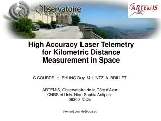
High Accuracy Laser Telemetry for Kilometric Distance Measurement in Space. C.COURDE, H. PHUNG Duy, M. LINTZ, A. BRILLET ARTEMIS, Observatoire de la Côte d'Azur CNRS et Univ. Nice-Sophia Antipolis 06300 NICE. clement.courde@oca.eu. Objectives.

E N D
High Accuracy Laser Telemetry for Kilometric Distance Measurement in Space C.COURDE, H. PHUNG Duy, M. LINTZ, A. BRILLET ARTEMIS, Observatoire de la Côte d'Azur CNRS et Univ. Nice-Sophia Antipolis 06300 NICE clement.courde@oca.eu
Objectives Absolute long distance measurement (~km) in vacuum with high accuracy For : Formation Flying telescope (Darwin (30µm of accuracy)) Alignement and monitoring of large structure (particle colliders or radio telescope) DARWIN Our goal Range : ~ 1km Accuracy : < 1µm Resolution: ~nm 2
Outline • T2M telemeter • Principle • Results • Iliade telemeter • Principle • Results
T2M Principle Corner cube Measurement path Λ=c/F Synthetic wavelength Amplitude Modulated beam mes Λ Adjustable frequency F Reference path ref t Δjref/mes Δjref/meslocked at 0 Calibration with K integer and c the speed of light Robust and simple system Accuracy limited by phase drifts and cyclic errors 4
T2M PrincipleElimination of systematic errors Exchange of the beams between the two photodiodes Corner cube Measurement path Λ=c/F Synthetic wavelength Amplitude modulated beam Reference path Adjustable frequency F Crosstalk Optical switching system PHD1 PHD2 Δj Cyclic errors are suppressed with the optical switching system Unbiased zero of phase difference 5
Optical isolator T2M Principle Corner cubes ASE SOURCE 1.55 µm Polarization controller 1 Amplitude modulator ref measure Frequency -meter VCO 13GHz PBS cube Optical switching system Polarization controller 2 DISTANCE Fibered PBS 2 kHz switch PHD Mixer HF HF phase-meter Δφ Telemetric signal Telemetric lock LI-A Lock-in Amplifier 6
T2M results Allan deviation of the Telemetric signal in open loop with a broadband source (ASE) 10 nm Allan deviation < 20 nm for 5s < times < 2000s At short measurement times by intensity noise of the source Probably limited At long measurement times by systematic error To identify parasitic interferences : Broadband source+modulator is replaced by the beat note of two single mode lasers shifted by 13 GHz
Systematic errors !!! T2M characterizationSearching for optical interferences 2µm 2µm Slow length scan 2 different cavity effects Telemetric signal Manual master laser wavelength scan 4GHz • FSR 4GHz • thickness 37mm (vacuum) or 25mm (n=1.5) • FSR 270MHz • thickness 56cm (vacuum) or 37cm (n=1.5) 5µm PBS cube Freq markers SOLUTION - PBS cube changed for a thick polarization beam splitter at 45° Manual master laser wavelength scan Telemetric signal 4GHz Freq markers Systematic errors lower than 1 µm 8
Iliade principle Time of flight measurement of optical pulses => Absolute distance measurement Combining 3 levels of increasing sensitivity: 0.1 mm Phase measurement of synthetic wavelength => relative distance measurement 15 mm 0.1 µm In PhD1 Phase measurement of optical wavelength => relative distance measurement 0.1 nm 1.55 µm Synthetic angular frequency Optical angular frequency
Iliade preliminary results Use of the interference figure : Varying allows to cover the « segment » Experiment « segment » for different positions with 0.5mm increments at a 1.5m Distance Simulation Varying L, All parameters fixed Deviations of 3.10-3 peak-peak Non-linearity in commercial oscilloscope used for data acquisition
Conclusion • T2M • Simple system with accuracy fixed by the frequency measurement • No optical stabilization • Systematic errors lower than 1 µm, to be confirmed • Stability below 20 nm for measurement times [5s,2000s] • Iliade • Principle of the measurement is confirmed • Limitations in phase measurements and in amplitude measurements caused by non linearity in the data acquisition system
Thanks to CNES ANR Thales Alenia Space région PACA and thank for your attention