Download
1 / 25
250 likes | 474 Vues
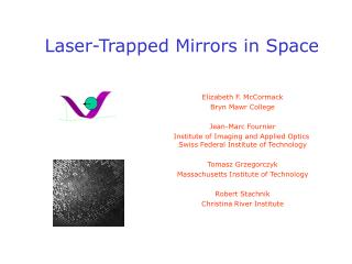
Laser-Trapped Mirrors in Space. Elizabeth F. McCormack Bryn Mawr College Jean-Marc Fournier Institute of Imaging and Applied Optics Swiss Federal Institute of Technology Tomasz Grzegorczyk Massachusetts Institute of Technology Robert Stachnik Christina River Institute. The Project.

E N D
Laser-Trapped Mirrors in Space Elizabeth F. McCormack Bryn Mawr College Jean-Marc Fournier Institute of Imaging and Applied Optics Swiss Federal Institute of Technology Tomasz Grzegorczyk Massachusetts Institute of Technology Robert Stachnik Christina River Institute
The Project Can Laser Trapped Mirrors be a practical solution to the problem of building large, low-mass, optical systems in Space? The Laser-Trapped Mirror (LTM) Concept NASA Goals Light-Induced Trapping Forces Role of Optical Binding Experimental Work Numerical Calculations Project Goals
CCD Mirror TRAPPED MIRROR Star Light Particle source Laser Mirror The LTM Design (Labeyrie, A&A, 1979) Standing wave of laser light traps particles
The LTM Concept Beams emitted in opposite directions by a laser strike two deflectors. Reflected light produces a series of parabolic fringe surfaces. Through diffractive and scattering forces, dielectric particles are attracted toward bright fringes, and metallic particles towards dark fringes. Ramping the laser wavelength permits sweeping of particles to the central fringe. Result is a reflective surface in the shape of a mirror of almost arbitrary size.
Advantages of the LTM Potential for very large aperture mirrors with very low mass (35 m--> 100g !!) and extremely high packing efficiency (35m--> 5 cm cube). Deployment without large moving parts, potential to actively alter the mirror’s shape, and flexibility to change mirror “coatings” in orbit. Potential for fabricating “naturally” co-phased arrays of arbitrary shape as shown at left. Resilience against meteoroid damage (self-healing). The LTM should be diffraction limited at long wavelengths. For a trapping wavelength in the visible, e.g. 0.5 m, and operation at 20 m, the “flatness” of the mirror will be better than /80.
NASA Goals Future NASA Optical Systems Goals and their relation to the LTM
Previous Work l Experiments by Fournier et al. in the early 1990’s demonstrated laser trapping of arrays of macroscopic particles along interference fringes: M. Burns, J. Fournier, and J. A. Golovchenko, Science 249, 749 (1990). Fournier et al. also observed that laser trapped particles can self-organize along a fringe due to photon re-scattering among the trapped particles resulting in "optical matter" (analogous to regular matter, which is self-organized by electronic interactions): M. Burns, J. Fournier, and J. A. Golovchenko, Phys. Rev. Lett. 63, 1233 (1989).
The Forces of Light Light fields of varying intensity can be used to trap particles. scattering force gradient force binding force Light reflection results in repulsion (scattering force). Light refraction results in attraction (induced dipole and field gradient forces). Strongly wavelength-dependent processes.
Trapping in a Gaussian Beam áFscatñ= 1/3 a2 k4áE2ñ áFgradñ = a . ÑáE2ñ Fgrad Fscat
Trap Strength Dipole interaction traps dielectric particles in regions of high field intensity. where a is the particle polarizability and I is the laser intensity. For two counter-propagating plane waves, the trap strength is: For 1 micron-sized particles with a reasonable index of refraction, n=1.6 and I expressed in Watts/m2: This is the challenge; this number is very small. Equivalent to a temperature of milliKelvins and an escape velocity of 10-4 cm/s. Compare to infrared background at T ~ 30K
Estimate of Evaporation Time At 30 K, background photons: ng ~ 106cm-3, l = 10-2 cm. DE ~ 10-34ergs/collision Given a cross-section, , for the interaction of silica with these photons, the rate of increase of the kinetic energy of a trapped particle is: dE/dt ~ 10-26 ergs/sec Integrating and evaluating for a 1 micron-sized particle, we get: where I is expressed in Watts/m2. with radius ~a: Particle size is critical. A respectable number: about 5 years for I = 1 Watt/m2 and ~ months for currently available laser intensities. 100 nm-sized particles --tevap ~ hours, will need damping.
Optical Binding Force Consider all fields: Incident and scattered, Near and far Pair of oscillators: Driven by fields and radiating like dipoles Solve for self-consistency
Optical Binding Potential Induced dipole moments in adjacent spheres will give rise to electromagnetic forces between the spheres. Burns, et al. give an approximation for this interaction energy: long-range interaction which oscillates in sign at l and falls off as 1/r. Calculations of this two-particle binding potential look encouraging. However, results are based on approximations not necessarily valid in the regime where particle radius ~ l. Need to explore this effect with no approximations, i.e., in the Mie scattering regime.
2 Beams 3 Beams Interferometric Templates
20 mm 20 mm 2.8 mm 2 mm One- and Two-Dimensional Traps 1500 traps 2 Beams 3 Beams
Observation of optical binding and trapping in a Gaussian beam 1 beam Auto-arrangement of 3 mm polystyrene beads at the waist of a Gaussian beam
2-Beam Interference filters CCD sample MO Voltage supply piezo-electric element 2 mm beads in motorizeddragged cell Fringes translation with piezo-electric element
3-Beam Interference imagingsystem CCD Piezo templategeneration intensity pattern
Optical Binding in 3-Beam Trap J.-M. Fournier, M.M. Burns, and J.A. Golovchenko, “Writing Diffractive Structures by Optical Trapping”, Proc. SPIE 2406 “Practical holography”, pp. 101-111, 1995. M.M. Burns, J.-M. Fournier, and J.A. Golovchenko, "Optical Matter", US Patent # 5,245,466, 1993
Project Goals • Demonstrate and characterize a small, floating LTM in water. • Develop and use computational algorithms to model an LTM which include all optical forces including optical binding effects. • Combine lab measurements with particle design and the computational models to obtain estimates for the mirror stability and quality, and for the laser power requirements in a vacuum environment.
Laser Trapped Mirrors in Space Artist’s view of Laser Trapped Mirror(NASA study by Boeing- SVS)