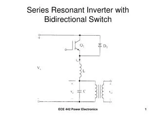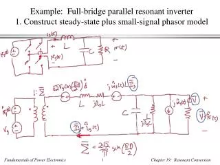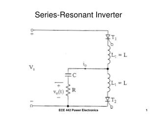
Class E Resonant Inverter
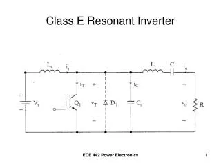
Class E Resonant Inverter. Mode 1 Operation – Turn Q1 ON at t = 0 Turn Q1 OFF when v o = 0 volts. For sinusoidal current,. The current through the transistor (switch) .

Class E Resonant Inverter
E N D
Presentation Transcript
Class E Resonant Inverter ECE 442 Power Electronics
Mode 1 Operation – Turn Q1 ON at t = 0 Turn Q1 OFF when vo = 0 volts ECE 442 Power Electronics
For sinusoidal current, The current through the transistor (switch) The switch is turned OFF when the output voltage becomes = 0, and the current is “transferred” to the branch containing the capacitor. ECE 442 Power Electronics
Mode 1 ECE 442 Power Electronics
Mode 2 Operation • Q1 is turned OFF • Diode D limits negative switch voltage ECE 442 Power Electronics
Capacitor current becomes When the switch current falls to zero, ECE 442 Power Electronics
Mode 2 ECE 442 Power Electronics
Waveform Summary ECE 442 Power Electronics
Example 8.9 • A class E inverter operates at resonance and has VS = 12 Volts and R = 10 Ω. • The switching frequency is 25 kHz. • Determine the optimum values of L, C, Ce, and Le • Use MultiSim to plot the output voltage v0 and the switch voltage vT for k = 0.304. Assume that Q = 7. ECE 442 Power Electronics
Optimum Parameters ECE 442 Power Electronics
Example 8.9 (continued) ECE 442 Power Electronics
Check the damping factor and resonant frequency ECE 442 Power Electronics
Example 8.9 ECE 442 Power Electronics
Switch Voltage Load Voltage ECE 442 Power Electronics
Class E Resonant Rectifier very large for power factor correction ECE 442 Power Electronics
Mode 1 Operation -- D1 OFF ECE 442 Power Electronics
Mode 2 Operation -- D1 ON ECE 442 Power Electronics
D1 switches OFF at 0 volts(0 voltage switching) • When the current iL falls to 0, the diode turns OFF. • When iL falls below Io, C discharges via D1 • At turn-off, iD=iL=0 and vD=vC=0. • The capacitor current, iC=C(dvC/dt)=0, or (dvC/dt) = 0. ECE 442 Power Electronics
Waveform Summary iL = iC + iD ECE 442 Power Electronics
Example 8.10 • A Class E rectifier supplies a load power of PL=400mW at Vo=4V. The peak supply voltage is Vm=10V. The supply frequency is f=250kHz. The peak-to-peak ripple on the dc output voltage is ΔVo=40mV. • Determine the values of L, C, and Cf. • Determine the rms and dc currents of L and C. ECE 442 Power Electronics
Example 8.10 (continued) • Choose C=10nF. • The resonant frequency will be 250kHz. • Details on the following slide ECE 442 Power Electronics
Example 8.10 (MultiSim) ECE 442 Power Electronics
Load Current 500 mAp-p Load Voltage 50 mVp-p ECE 442 Power Electronics