Download

1 / 21
220 likes | 351 Vues
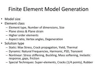
Finite Element Model of a Magnet Driven Reed Switch. Bryan M. LaBarge 1 and Dr. Ernesto Gutierrez-Miravete 2 1 Gems Sensors and Controls, 2 Rensselaer at Hartford. Scope. Use COMSOL to predict and visualize a magnetic field Use further processing to determine field strength

E N D
Finite Element Model of a Magnet Driven Reed Switch Bryan M. LaBarge1 and Dr. Ernesto Gutierrez-Miravete2 1Gems Sensors and Controls, 2Rensselaer at Hartford
Scope • Use COMSOL to predict and visualize a magnetic field • Use further processing to determine field strength • Correlate field strength to reed switch operation
Background • Magnet/reed switch systems are used extensively for proximity sensing • Ability to predict reed switch operation reduces testing time, time to market • Knowing magnet strength at any point allows designer to focus on reed switch selection
Governing Equations • Maxwell’s Equations • Magnetization Equation B = m(H+M)
Model Creation • 2-D (r-z coordinate) magneto-static analysis • Magnet centerline bounds model • Magnet modeled as iron, bounded by air • M = 1.6x10⁵ A/m • Relative permeability (m) = 4000 • Elements: 15,472 (triangular, 7859 nodes) • Static, stationary solver • Output = Gauss (r-, z-, normal direction)
Model Validation • Magnet mounted to XY table, Gauss probe stationary, 3.9 mm parallel to magnet centerline • Measurements taken every 0.3 mm • Results plotted vs. COMSOL output
Procedure (in brief) • Export COMSOL data to EXCEL • Use EXCEL data as look-up table • Calculate coordinates of switch movement along an arc • Calculate magnetic field at coordinates using look-up table • Determine switch operation
Procedure (continued…) • COMSOL data exported to EXCEL • 0.3 mm resolution in (x,y) coordinates • Magnet/Switch location measured relative to pivot point (origin) • Open/closed positions of switch measured for later reference
Procedure (continued…) • xmax defines arc radius • Coordinates calculated on 0.02 mm resolution in x-direction • Coordinates are interpolated from the look-up table to assign Gauss values to points on the arc • Arc coordinates/Gauss values become second look-up table
Results • Reed switches are tested using a test coil, measuring operation in terms of Ampere-Turns (AT) • AT = I n • I = current; n = number of coil turns • Test switch open/closed values: • Open = 29.1 AT • Closed = 18.7 AT
Results (continued…) • Prior empirical testing shows Gauss/AT correlation • G = 0.533AT – 0.857 • Open = 14.7 G • Closed = 9.12 G
Results (continued…) • Model Verification • Red = COMSOL, Blue = Empirical
Results (continued…) • COMSOL contour plot, normal direction
Results (continued…) • COMSOL contour plot, z- direction
Results (continued…) • Using the values of Gauss on switch arc and the Gauss values for switch operation, switch location can be interpolated. • Example: 29 AT = 14.57 G = (15.47, 8.72) mm
x, closed y, closed x, open y, open Model 15.47 8.72 14.98 10.96 Observed 15.34 8.97 14.83 10.82 Error 0.84% -2.87% 1.00% 1.27% Results (continued…) • Actual switch points compared to calculated switch points
Conclusions • COMSOL model agrees with empirical results to within 2% • Increased error in y than x due to geometry
Conclusions • Application requires 20o maximum angle, switch should operate at 10o • Model says switch will open at 18.3o and close at 9.9o • Decrease in AT on switch will close switch over full arc.
Conclusions • Model is a simplification of actual system • Further work can be done to model effects of reed blades • Speaker’s first COMSOL model