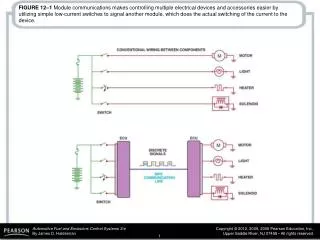
3 modules 1.5 kW each redundancy n+1 current sharing interleaved operations
20 likes | 340 Vues
+. C 4. Q 4. 1. L. T 1. IBVD. 0.88. +. i L. IB Converter. 0.9. IB Converter. +. V out. T 3. Q 3. C o. C 3. -. 0.84. Main DC/DC Converter. Main DC/DC Converter. V in. 0.8. L. +. Single Buck. C 2. 0.8. +. Q 2. T 4. +. 0.7. V CC. i T2. V DC. C 1. DUT. 0.76.

3 modules 1.5 kW each redundancy n+1 current sharing interleaved operations
E N D
Presentation Transcript
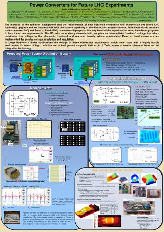
+ C4 Q4 1 L T1 IBVD 0.88 + iL IB Converter 0.9 IB Converter + Vout T3 Q3 Co C3 - 0.84 Main DC/DC Converter Main DC/DC Converter Vin 0.8 L + Single Buck C2 0.8 + Q2 T4 + 0.7 VCC iT2 VDC C1 DUT 0.76 T2 vc 0.6 iDUT + Q1 C1 0.72 LDO Converter LDO Converter LDO Converter LDO Converter niPOL Converter niPOL Converter LDO Converter LDO Converter LDO Converter niPOL Converter LDO Converter niPOL Converter LDO Converter LDO Converter LDO Converter niPOL Converter LDO Converter niPOL Converter Rshunt 0.5 DRIVER 0.2 0.4 0.6 0.8 1.0 1.2 1.4 1.6 2.5 1 1.5 2 3 ni Regulated Power Converters POL POL POL POL POL POL POL POL POL POL POL POL POL POL POL POL POL POL Vout = 12V 4 layers 13 cm 10 layers 2 concentric turns in each layer 4.71mm 22 layers Efficiency (Bext = 0) 4 layers Transient response S1 S2 L1 Efficiency comparison (Bext = 0) + + S4 Uin Uo Co R UC1 C1 - - L2 S3 D<50% Uo = UinD/2 Output power [kW] Output current [A] Vout Iload Power Converters for Future LHC Experiments Apollo collaboration, funded by I.N.F.N. Italy M. Alderighi(1,6), M. Citterio(1,*), S. Latorre(1), M. Riva(1,8), M. Bernardoni(3,10), P. Cova (3,10), N. Delmonte(3,10), A. Lanza(3), R. Menozzi(10), A. Costabeber(2,9), A. Paccagnella (2,9), P. Tenti(2,9), F. Sichirollo(2,9), G. Spiazzi(2,9), M. Stellini(2,9), S. Baccaro(4,5), F. Iannuzzo(4,7), A. Sanseverino(4,7), G. Busatto(7), V. De Luca(7) (1) INFN Milano, (2) INFN Padova, (3) INFN Pavia, (4) INFN Roma, (5) ENEA UTTMAT, (6) INAF, (7) University of Cassino, (8) UniversitàdegliStudidi Milano, (9) University of Padova, (10) University of Parma, CRATE CRATE UGS [1V/div] UGS [1V/div] Card #1 Card #1 Card #3 Card #2 Card #2 Card #3 UDS [20V/div] -IDS [1A/div] (*) Presenter The increase of the radiation background and the requirements of new front-end electronics will characterize the future LHC luminosity upgrade and are incompatible with the current capability of the distribution systems in use. An isolated dc-dc resonant main converter (MC) and Point of Load (POL) converters deployed at the very heart of the experimental setup have been proposed to face these new requirements. The MC, with redundancy characteristic, supplies an intermediate “medium” voltage bus which distributes the voltage to the electronic front-end and read-out boards, where non-isolated Point of Load converters are implemented for precise voltage adaptation and regulation. In Large Hadrons Collider applications the design of these electronics equipments, which must cope with a highly hostile environment in terms of high radiation and a background magnetic field up to 2 Tesla, opens a severe tolerance issue for the integration technology. -IDS [1A/div] 12V10% UDS [20V/div] Intermediate DC bus 5V10% -poff(t) POL Converter with high step-down ratio Time [10ns/div] Time [10ns/div] Proposed Power Supply Distribution System Test case: ATLAS Liquid Argon (LAr) Calorimeters • Characteristics: • Main isolated converter with N+1 redundancy • High DC bus voltage (12V or other) • Distributed Non-Isolated Point of Load Converters (niPOL) with high step-down ratio Regulated DC bus 48Vdc10% 280 Vdc 280 Vdc Regulated C bus 48V5% Non-Isolated PoL Converter Interleaved Buck with Voltage Divider - IBVD 12V5% • Characteristics: • Zero voltage switch turn on • High step-down ratio • Reduced switch voltage stress (Uin/2) • Interleaved operation with automatic current sharing and ripple cancellation Main converter • 3 modules 1.5 kW each • redundancy n+1 • current sharing • interleaved operations • Switch In Line Converter - SILC • phase shift operation • ZVS transitions • high efficiency • reduced switch voltage stress • high frequency capability IBVD • Specifications: • Input voltage: Ug = 12 V • Output voltage: Uo = 2.5 V • Output current: Io = 3A • Operating frequency: fs = 1 MHz • 350 nH air core inductors • Dimensions: L = 6cm, W = 4.2cm Small signal dynamics EPC GaN MOSFET 33 cm X-rays for checking the solder quality Air bubbles Measured DUT voltage and current during switching intervals 7 cm Rshunt = 85 mW Output voltage response to a load step change (25 A 37 A) Planar transformer Turn on interval @ Vcc = 100V, IDS = 0A Turn off interval @ Vcc = 100V, IDS = 5A Main converter module thermal design • 3D Finite Element Model (FEM) • FE modeling of the main heating components: • Input power MOSFETs • Output diodes • Inductor • Planar transformer • Thermal measurements 1 • Thermal characterization on single components, to validate models • Thermal design • Designed advanced solutions to improve heat exchange: • Power MOSFETs mounted on IMS board • ISOTOP diode isolated package directly mounted on baseplate • Copper thermal layers for transformer core cooling • Silicone gap filler for transformer windings cooling • Thermal simulation and measurements 2 • Preliminary thermal measurements on the air cooled whole converter Turn ratios 10:10:2: 4 units connected in parallel Transformer behavior in stationary Magnetic Field orange = primary winding voltage blue = secondary winding voltagemagenta = primary winding current green = snubber current (proportional to the switching losses). Bstat. 789 Gauss Bstat. 2591 Gauss Specific activities are addressed to obtain a ferromagnetic nucleus able to produce high magnetic field with limited current stimulations. The base elements consist in a mixture of Fe and Si powders blended in precise ratio (percentage of organic additives, and blending methodology are key points) in order to make a ferromagnetic compound injection moulded in test sample. • Final requirements • Main converter output power = 3x1 kW • Case dimensions: 150 x 402 x 285 mm3 • Max case temperature = 18°C • Water cooling system • delivery = 1.9 l/min • p = 350 mbar • Tinlet = 18°C • Toutlet ≤ 25°C