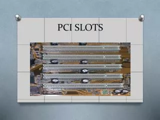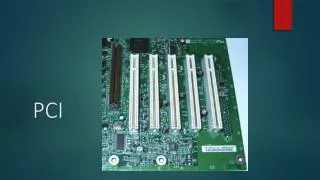
PCI
PCI. Older PC Implementations. Newer PC Implementations. PCI Overview. PCI Features. 32-Bit or 64-Bit address and data 66 or 33 down to 0 MHz synchronous operation Single or multiple bus masters Reflected bus signaling Stepped signaling Bus parity error reporting


PCI
E N D
Presentation Transcript
PCI Features • 32-Bit or 64-Bit address and data • 66 or 33 down to 0 MHz synchronous operation • Single or multiple bus masters • Reflected bus signaling • Stepped signaling • Bus parity error reporting • 5 or 3.3 volt operation • Cache support • JTAG testing
PCI Bus • Bus Signals • Bus Commands • Bus Transactions • Arbitration
Required Pins Optional Pins AD[31::00] AD[63::32] Address & Data 64-Bit Extension C/BE#[3::0] C/BE#[7::4] PAR PAR64 REQ64# FRAME# ACK64# PCI TRDY# M66EN COMPLIANT Interface IRDY# Interface DEVICE LOCK# Control Control STOP# DEVSEL# Interrupt A-D# IDSEL Clkrun# SBO# Arbitration REQ# Cache (masters only) SDONE Support GNT# PERR# Error TDI Reporting SERR# TDO JTAG CLK TCK System (IEEE 1149.1) TMS RST TRST# Present 1-2 PCI Pin List PCI Bus Signals
PCI bus access • PCI is a Multimaster Bus • All transactions initiated by a master • All transactions to/from a target
PCI Bus Control Signals • FRAME# • driven by master to indicate transfer start and end • IRDY# • driven by master to indicate it is ready to transfer data • TRDY# • driven by target to indicate it is ready to transfer data
CLK 2 3 4 5 6 7 8 9 1 FRAME# AD Address C/BE# Command IRDY# GNT# Bus Idle Bus transaction start
C/BE [3::0]# Command Type 0000 Interrupt acknowledge 0001 Special Cycle 0010 I/O Read 0011 I/O Write 0110 Memory Read 0111 Memory Write 1010 Configuration Read 1011 Configuration Write 1100 Memory Read Multiple 1101 Dual Address Cycle 1110 Memory Read Line 1111 Memory Write and Invalidate PCI Command Definition
CLK FRAME# ADDRESS DATA-1 DATA-2 DATA-3 AD BUS CMD BE#’S C/BE# IRDY# TRDY# DEVSEL# PCI Bus Read
Arbitration • Arbitration is access based • Master must arbitrate for each bus access • Central arbitration scheme • Each master has a unique request and grant signal • Arbitration is hidden • Occurs during previous bus cycle
Bus Parking • Parking permits the arbiter to select an agent, by asserting its GNT#, when no other agent is using or requesting the bus • The arbiter determines how this selection is made • Fixed, Last Used, …, or None
Keyway 5V 32-Bit Connector 33 MHz 5V 64-Bit Connector 3.3V 32-Bit Connector 33/66 MHz 3.3V 64-Bit Connector Rear Front PCI Card Connectors
Dual-Voltage Card • 5 Volt Card • 3 Volt Card • 3 Volt • 5 Volt • System • System • Key near backpanel • Key away from • backpanel 5 V To 3.3 V Migration Path
System Initialization • Configuration allows software (BIOS) to initialize the system • Each device has configuration registers • At power up software scans bus(es) • Software analyses system requirements • Configuration registers are set to configure individual devices
Configuration Types • Specific bus commands • configuration read (C/BE# = 1010) • configuration write (C/BE# = 1011) • Type 0 • local PCI bus • IDSEL line indicates device • address field indicates register • Type 1 • remote PCI bus (through bridge) • address field indicates bus, device and register
Device ID Vendor ID 00 Command Status 04 Rev Class Code 08 Latency Timer Header Type Cache Line Size BIST 0C 10 Base Address 0 14 Base Address 1 18 Base Address 2 Base Address 3 1C Base Address 4 20 24 Base Address 5 Cardbus CIS Pointer 28 Subsystem ID Subsystem Vendor ID 2C Expansion ROM Base Address 30 Reserved 34 38 Reserved Interrupt Pin Interrupt Line Max_Lat Min_Gnt 3C Configuration Space Header
Figure: Type 0 PCI Configuration Cycle Figure: Type 1 PCI Configuration Cycle