PCI
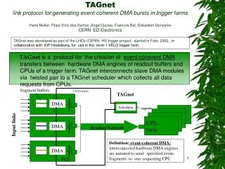
TAGnet is a protocol for the creation of event-coherent DMA transfers between hardware DMA engines of readout buffers and CPUs of a trigger farm. TAGnet interconnects slave DMA modules via twisted pair to a TAGnet scheduler which collects all data requests from CPUs. fragment buffers.

PCI
E N D
Presentation Transcript
TAGnetis a protocol for the creation of event-coherent DMA transfers between hardware DMA engines of readout buffers and CPUs of a trigger farm. TAGnet interconnects slave DMA modules via twisted pair to a TAGnet scheduler which collects all data requests from CPUs. fragment buffers TAGnet DMA Scheduler requests CPU farm Input links DMA Readout Network DMA PCI TAGnet link protocol for generating event-coherent DMA bursts in trigger farmsHans Muller, Filipe Vinci dos Santos, Angel Guirao, Francois Bal, Sebastien GonzalveCERN ED Electronics TAGnet was developed as part of the LHCb (CERN) HS trigger project, started in Febr. 2002, in collaboration with KIP Heidelberg, for use in the level-1 VELO trigger farm. Twisted pair Definition: event-coherent DMA: interconnected hardware DMA engines are initiated to send specified event-fragments to one requesting CPU
Features of Event-coherent DMA • CPU requests new events from scheduler whilst processing previous one • cheap implementation ( twisted pair, FPGA logic, PCI card ) • added functionality via “message-TAGs” ( bufferchecks, common Xon/Xoff ) • highest possible use of the network raw bandwidth ( hardware timing ) • no spurious arrivals of event fragments: all arrive concatenated in time • no problem with crashing farm CPUs ( just 1 less ) • no worst-case destination buffer like for round-robin ( 2 buffers sufficient ) • no problem with very large variations in CPUtime per event
32 CPU-cluster prototype at KIP, COTs PCs 6 Gbit/s network, shared memory Eventbuilding I/O requirement 4 kbyte @ 1 MHz ( 4 Gbyte/s): • very small payloads produced per link < 40 byte • very high frequency (up 1.1 MHz ) • farm of COTS computers ( PCI bus I/O ) Baseline Approach : Measured at KIP cluster: Hardware DMA via PCI to: (1) local, (2) remote memory (3)Software DMA local memory • aggregate 4 -> 1 links for network payloads >= 128 byte and use a minimal overhead format1 • use “hardware eventbuilding” in “memory” ( shared memory farm ) • use PCI memory access mechanism for memory-memory copy ( physical PCI address for DMA mapping to remote memory ) 1 248 Mbyte/s 2 3 > 128 byte payloads LHCb VELO trigger problem T A G N E T: schedule memory-directed DMA’s in an “event-coherent” way 1. STF format 5 % overhead )
11 bit Buffer Adr. 7 b Info 7 b Hamming class type instructions 7 b Dcount 7 b SourceID 12 bit ID / data 63 TAG: a 64 bit of transfer information 1 First 1 Force 1 Done 1 Reserved 1 Reserved 1 Reserved Simplified: Command local DMA buffer addr. CPU Identifier What is a TAG • More: • 4 TAG classes • 4 TAG types • 7 bit Done counter • 7 bit Source Module ID • 7 bit Coded information • 7 bit Error correcting code
TAGs on a 16 bit bus • 64 bit TAGs are transmitted in four 16 bit words followed by 1 idle • 17th bit (Flag) used to delimit “TAG heartbeats” ( 1111011110..) • Error-correcting Hamming code in the last word
Bus 16 bit serial link (CAT5 twisted pair) 3 * 175 Mbit/s + 1 * 25 Mbit/s TAG in LHCb Readout Unit: TAG out FPGA TAGs over narrow links Logical 64 bit
TAGnet slave VHDL design and synthesis for FPGA simplified block diagram: OUT IN • “Paket Reception” stores all incoming TAGs in 64 bit bypass register • “Packet FiFo” only stores TAGs which are directed to the slave • “Decoding& Execution” takes desired action • “DMA-engine” gets loaded with source/destination + starts ation • “Packet-Transmission” copies used TAGs back into the TAGnet ring
TAG heartbeats: 16-bit words in 11110 clock beats Hbeats contain valid or invalid TAGs 4 3 2 1 Max. 5 MHz TAGs Idle Idle Idle 25 MHz clock Heartbeat on TAGnet links 5 clocks/ Hbeat • synchronous “heartbeat” on link 1111011110.. (bit 17) • Heartbeat is always on, carrying valid or invalid TAGs • One “heartbeat” consists of 4 words + 1 Idle (= 5 clocks) • 1st word contains important class/type/command bits Heartbeats Slaves Scheduler TAGnet ring Heartbeat check: physical link layer heartbeat transport
N Slaves 1 Master tags Scheduler TAGnet ring Twisted pair Readout cards PCI card deserializer serializer FPGA (DMA) SLINK SDRAM FPGA serializer PCI bus memory bus PCI bus Network Interface Subevent buffer Readout network TAGnet components:
11 bit Buffer Adr. 7 b Info 7 b Hamming class type instructions 7 b Dcount 7 b SourceID 12 bit ID / data 63 1 First 1 Force 1 Done 1 Reserved 1 Reserved 1 Reserved Tag classes invalid, consumeable. These TAGs are freely consumeable TAGs which can be used by any TAGnet slave to create valid TAGs at it’s output valid, not consumeable. These TAGs fall into the type of directed scheduler messages, created normally by a TAGnet slave. They contain message information ( like errors ) for the scheduler and hence must not be consumed by other TAGnet slaves. valid, consumeable. These TAGs fall into the types: undirected command, undirected message, directed slave message and hence contain important scheduler information (command / address / message ) to be consumed by TAGnet slaves.
11 bit Buffer Adr. 7 b Info 7 b Hamming class type instructions 7 b Dcount 7 b SourceID 12 bit ID / data 63 1 First 1 Force 1 Done 1 Reserved 1 Reserved 1 Reserved Tag types undirected slave message (M-TAG) of class VALID CONSUMABLE. These TAGs send an encoded message to all slaves directed slave message (M-TAG) of classVALID CONSUMABLE.These TAGs send command and data to one slave directed scheduler message (M-TAG) of class VALID NON CONSUMEABLE. These TAGs send an encoded message (error or other) from a slave to the scheduler
Requestx C-TAG Source buffers CPUx RU Scheduler Destination CPU Readout Network Tagnet Slave FPGA Tagnet Master FPGA C-TAG hardware C-TAG buffer Event fragment buffer Command execution 64 bit bypass TAGnet link DMA Host PCI bus Slave output bus C-TAGs -> event-coherent DMA C-TAGs are the vast majority of TAGs. Each C-TAG creates 1 event-coherent DMA burst to a requesting CPU: all DMA-slaves are triggered to load identical Source/Destination in their DMA engines and to transmit their data. Result: a fast succession of subevents to the requester CPU. event Event-coherent DMA transfer
11 bit Buffer Adr. 7 b Info 7 b Hamming class type instructions 7 b Dcount 7 b SourceID 12 bit ID / data 63 1 First 1 Force 1 Done 1 Reserved 1 Reserved 1 Reserved Message examples of “Directed 1 Slave” M-TAG 0 0 0 SELECT: select a TAGnet slave operation mode contained in the 6 bit info field 1 0 0 FLUSH ALL: flush all buffers, reset pointers Message examples of “Undirected Slave” M-TAG (to all slaves) 0 0 0 DIAG: request for Slave Info via M-TAG as specified in Coded INFO field 1 0 0 FLUSH ALL: flush buffers, reset their pointers Message examples of “Undirected Slave” M-TAG (slave to scheduler) 0 0 1 ERROR ( error type decoded in INFO field ) 1 0 0 THROTTLE request Message Tags ( M-TAG) Message TAGs (M-TAGS) coexist with C-TAGs for messages between slaves and scheduler. Generated by the scheduler software, M-TAGs are not time critical.
CPUx,y,x Aggregation buffers sh. memory • Shared memory eventbuilding features: • DMAs “write-through” to shared CPU memory (red) • One event-coherent burst to 1 CPU per C-TAG • events auto-closed by fixed Nr of event-frames • Shared memory TAGnet features: • CPUx,y,z send request to memory block (blue) • CPU’s share 1 single scheduler Tagnet in shared-memory farms TAGs may be used for event-coherent Event-building in any system. Shared-memory: for high rate (triggers) 1.) perform high-rate eventbuilding using memory-memory copy ( may require blocksize aggregation ) 2.) create TAGs at high rate on CPU demand CPU-Farm TAGnet CPU Scheduler mem S/N bridge DMA network PCI NIC DMA Input links DMA NIC PCI
C-TAG Readout Unit: PCI 32 @ 33 MHz ( ! ) Buffer 1 DMA1 CPU Memory NIC 6 Gbit Network NIC DMA2 Buffer 2 2*DMA->NIC->Network NIC->PCI->Memory NIC receives 128 byte payload PCI64@66 Network IN NIC uses PCI write combining DMA1+DMA2 2 *64 byte Network 6 Gbit/s PCI burst to memory PCI32@33 PCI64@66 Extrapolated ¼ to PCI64@66MHz Outgoing 128 byte payload in 200ns 2 MHz E.C. DMA bursts Network 6 Gbit/s Network BW used at 40% with 2 MHz of 128 byte bursts DMA measurements PCI to PCI over 6 Gbit/s network PCI 64 @ 66 MHz 4 * Slink
TAGnet Scheduler • Hardware: FPGA logic in PCI card • serialize TAGs to twisted pair link ( mezzanine card ) • monitor TAGnet ring alive status (heart/errorbeats/clock) • auto-generation of next event-buffer ( default +1 ) • monitor status of outstanding and returning C-TAGs • timeout for C-TAG return ( programmable via a control register) • decode errors received via M-TAGs from slaves • error reporting via interrupts • accumulation of log-files from returning M-TAGs (SDRAM buffer) • Software: C-Tag PCI driver, M-Tag control, Error handling • PCI driver ( Linux & W2000 ) • initialize/configure all TAGnet slaves & disable (throttle) triggers during setup • Creation of C-TAGs from request table at rates >= trigger rate • creation of special C-Tags ( Reset, Align , Flush ) • use M-TAG functions for all setup / monitoring/ diagnostic tasks • read / check log-files from returning M-TAGs ( including error TAGs from slaves) • routines for interrupt error handling • regular source buffer verifications / flushing via M-TAGs
PCI master/ slave + Config. Registers RAM CPU request array ( Priority encoder ) Host PCI bus ADD Address decode C Throttle FF Link HB check TAG type decoder Done Count=0 ? Make C-TAG Error handling C-TAG ckeck M-TAG buffer M-TAG check IRQ M next clear Donebit= Max.Nr. Slaves 4*16 bit TAG beats Scoreboard of busy network channels TAGnet ring clear Serializer 25 MHz Heartbeat n TAGnet slaves SDRAM logfiles De-serializer Throttle FPGA Scheduler hardware
Project status DONE Under Progress Under Progress Planned Scheduler software • C-TAG creation: • CPU request = 12 bit Identifier • at 1 MHz trigger rate ( LHCb ) minimum C-TAG request bandwidth is 2 Mbyte/s • Burst-mode PCI driver: transmit CPU request from memory to scheduler’s buffer @ 1 MHz • M-TAG creation: • assemble any class/type of an M-TAG on user request • send M-TAG • M-TAG result collection: • readout of M-TAG logfile from SDRAM • identify returned M-TAG (Type, ID , Command ) & read result • Error handling: • PCI interrupt handler • Interrupt code register PCI
Scheduler host: One PC of cluster 2 D CPU cluster Scheduler C-TAG software LINUX with shared memory 0 0 1 0 0 0 0 1 0 0 0 0 0 0 0 1 0 0 1 0 0 0 0 0 0 Row Nr 0 Row Nr 1 Readout Units Memory scan Requests: Copy to mapped memory DMA Row Nr n Make 32 bit bitmaps, suppress empty rows cpu Mapped memory Row Nr 3 Row Nr 1 Row Nr 0 00100 00100 10010 C-TAGs HARDWARE (PCI Card ) SDRAM PCI burst to scheduler card De- serial Slink. SDRAM Ctrl. PCI bus serial PCI glue Slink32 FPGA logic C-TAG software loop for 2D shared memory cluster
Make request blocks and send to PCI: 31 0 23 31 Request bits of CPU in row Row-Nr PCI bursts, 16 *32 bit PCI bus activity mixed bursts and single words C-TAG loop timing result Emulation of request loop 16 * 16 farm on “o ld PC” ( PCI bus 32 bit 33 MHz): Measured Xfer to PCI: 1,4 us for up to 24 CPU request bits Safe to say that >> 1 MHz applies for faster PC with 64 bit 66 MHz PCI Local segment (id=0x80400, size=1024) is created. Local segment (id=0x80400, size=1024) is created. Local segment (id=0x80400) is mapped to user space. The physical address for local segment is :2f6000 Local segment (id=0x80400) is available for remote connections. Waiting for the DMA transfer to be ready .... Node 8 received interrupt (0x0) DMA transfer done! Client data: 0 0 0 0 0 0 0 0 0 0 0 0 0 0 0 0 0 0 1024 1024 0 0 0 0 0 0 0 0 0 0 0 0 0 0 0 0 0 0 0 0 0 0 0 0 0 0 0 0 0 0 0 0 0 0 0 0 0 0 0 0 0 0 0 0 … Detecting Orca on 2:f....[ OK ] Physical address = 2f6000 duration for the writing of 16*1000 32bits WORDS : 22843 usec
Summary • TAGnet is a 64 bit protocol which sends TAGs at up to 5 MHz rate in a ring of DMA slaves • Interconnection within a TAGnet ring is based on twisted pair (CAT5 ) • C-TAGs organize event-coherent DMA transfers on CPU demand • M-TAGs serve for initialization, error reporting and control • 4 TAGnet classes and 4 TAGnet types ( 16 flavors ) • TAGnet scheduler is a PCI card which receives CPU requests • First experimental TAGnet slave implementation in LHCb Readout Unit ( FPGA ) • First experimental TAGnet master implementation via programmable PCI-FLIC card • software loop “CPU-requests to scheduler” demonstrated to work at more than 1 MHz • successive “event-coherent DMA” measured at rates up to 2 MHz for 128 byte payloads
FPGA SDRAM 64 bit PCI @ 66 MHz Interfaced via Slink connector Slink I/O card (EP-ED) TAGnet IN • reprogrammed for TAGnet • 32 bit Slink connector • RJ45 standard network link TAGnet OUT PCI card with Tagnet mezzanine FLIC card ( EP-ED) • lowcost FPGA card • very fast host bus IF • 64 Mbyte SDRAM • drivers for Linux/Windows • programmable Slink IF
TAGnet on LHCb Readout Unit Dual DMA engines Readout Network TAGnet Networked Embedded CPU Subevent buffer Input Links 4*Slink