Download

1 / 54
540 likes | 699 Vues
Amateur Radio Technician Class Element 2 Course Presentation. ELEMENT 2 SUBELEMENTS T1 - FCC Rules, station license responsibilities T2 - Control operator duties T3 - Operating practices T4 - Radio and electronic fundamentals T5 - Station se 1 1 tup and operation

E N D
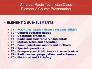
Amateur Radio Technician ClassElement 2 Course Presentation • ELEMENT 2 SUBELEMENTS • T1 - FCC Rules, station license responsibilities • T2 - Control operator duties • T3 - Operating practices • T4 - Radio and electronic fundamentals • T5 - Station se11tup and operation • T6 - Communications modes and methods • T7 - Special operations • T8 - Emergency and Public Service Communications • T9 - Radio waves, propagation, and antennas • T0 - Electrical and RF Safety
Operating practices T3A • Choosing an operating frequency • You should listen to determine if the frequency is busy when selecting a frequency on which to transmit. • Calling CQ • You indicate you are looking for any station with which to make contact by calling CQ followed by your callsign. • The meaning of the procedural signal "CQ" is: Calling any station. • The brief statement, simply saying your call sign, is often used in place of "CQ" to indicate that you are listening for calls on a repeater. Don’t call CQ on the repeater.
Operating practices T3A • Calling another station • If you know the station's call sign, say the station's call sign then identify your own station when calling another station on a repeater. • You should transmit the other station’s callsign followed by your callsign when responding to a call of CQ. • You should avoid using cute phrases or word combinations to identify your station because they are not easily understood by some operators. • You should use the International Telecommunication Union (ITU) phonetic alphabet when identifying your station because the words are internationally recognized substitutes for letters.
Operating practices T3A • Test transmissions • An illegal unidentified transmission includes a brief test transmission that does not include any station identification. • An amateur must properly identify the station when making a transmission to test equipment or antennas. • Station identification is required at least every ten minutes and at the end of every transmission – even test transmissions
Operating practices T3B • Use of minimum power • An amateur must use the minimum transmitter power necessary to carry out the desired communication. • This is the rule for: • Repeaters • Simplex • HF • ANYTHING ELSE
Operating practices T3B • Band plans • A band plan is a voluntary guideline, beyond the divisions established by the FCC for using different operating modes within an amateur band. • Band Plans are voluntary guidelines for efficient use of the radio spectrum. • The amateur community developed the band plans used by amateur radio operators.
A Band Plan is a voluntary guideline for using different operating modes within an amateur band. • 50.000-50.100: CW - No voice modes allowed per FCC section §97.305 • 50.060-50.080: CW/Beacon Subband • 50.100-50.300: Phone (SSB), etc. (no FM voice) • 50.100-50.125: DX Window • 50.300-50.600: All modes (simplex)50.600-50.800: Digital modes (e.g. Packet)50.800-51.000: Radio Control (R/C)51.000-51.100: "Pacific DX window" (SSB/CW)51.120-51.480: 6 Meter FM Repeater Inputs (areas w/500 KHz split)51.500-51.600: Simplex FM, 6 channels: 51.500, 51.520, 51.540, 51.560, 51.580, and 51.60051.620-51.980: 6 Meter FM Repeater Outputs (areas w/500 KHz split)52.000-52.480: 6 Meter FM Repeater Inputs (for 500 KHz and 1 MHz split) • Note: 52.525, 52.400, 52.040, and 52.020 are widely used for simplex operation with 52.525 being the "national simplex" frequency. • 52.500-52.980: 6 Meter FM Repeater Outputs53.000-53.480: 6 Meter FM Repeater Inputs and Repeater Outputs53.500-53.980: 6 Meter FM Repeater Outputs
Operating practices T3B • Repeater coordination • The recognized frequency coordination body is in charge of the repeater frequency band plan in your local area. • The main purpose of repeater coordination is to reduce interference and promote proper use of spectrum.
Operating practices T3B • Mode restricted sub-bands • The 6-meter, 2-meter, and 1-1/4-meter bands available to Technician class licensees have mode restricted sub-bands. • The only emission mode that is permitted in the restricted sub-band at 50.0-50.1 MHz is CW. • The only emission mode that is permitted in the restricted sub-band at 144.0-144.1 MHz is CW. • The emission modes that are permitted in the restricted portion of the 1-1/4-meter band are CW and Data.
FCC Rules and Station Licensee Responsibilities T1C • Authorized frequencies (Technician) • The frequency, 52.525 MHz, is within the 6-meter band. • The frequency, 146.52 MHz, is within the 2-meter band • The frequency, 223.50 MHz is within the 1.25 meter band. • The frequency, 443.350 MHz, is within 70-centimeter band • The frequency, 1296 MHz, is within the 23 Centimeter band • A good way to figure this out is 300/f=Band
Operating practices T3B • Accountability • The transmitting station is accountable if a repeater station inadvertently retransmits communications that violate FCC rules. • Obscene • Ciphers not permitted • Unidentified communications
Operating practices T3C • Courtesy and respect for others • The proper way to break into a conversation between two stations that are using the frequency is to say your call sign between their transmissions. • Proper repeater operating practice: • Monitor before transmitting and keep transmissions short • Identify legally • Use the minimum amount of transmitter power necessary
Operating practices T3C • Courtesy and respect for others (cont) • Before responding to another stations call, make sure you are operating on a permissible frequency for your license class. • No frequency will be assigned for the exclusive use of any station and neither has priority. This rule applies when two amateur stations want to use the same frequency. • If you hear a newly licensed operator that is having trouble with their station you should contact them and offer to help with the problem. • When circumstances are not specifically covered by FCC rules the general operating standard of good engineering and good amateur practices must be applied to amateur station operation.
Operating practices T3A • Sensitive subject areas • Amateur radio operators should avoid the use of racial or ethnic slurs when talking to other stations because it is offensive to some people and reflects a poor public image on all amateur radio operators. • These types of subjects are not prohibited communications while using amateur radio: • Political discussions • Jokes and stories • Religious preferences
Operating practices T3A • Obscene and indecent language • Indecent and obscene language is prohibited in the Amateur Service. • Because it is offensive to some individuals • Because young children may intercept amateur communications with readily available receiving equipment • Because such language is specifically prohibited by FCC Rules • There is no official list of prohibited obscene and indecent words that should not be used in amateur radio.
Operating practices T3D • Interference to and from consumer devices • Receiver front-end overload is the result of interference caused by strong signals from a nearby source. • The owner of the television receiver is responsible for taking care of the interference if signals from your transmitter are causing front end overload in your neighbor's television receiver. • A break in (or bad connection to) a cable television transmission line may result in TV interference when the amateur station is transmitting, or interference may occur to the amateur receiver. • The major cause of telephone interference is the telephone was not equipped with adequate interference protection when manufactured.
Operating practices T3D • Interference to and from consumer devices (cont) • Receiver front-end overload is the result of interference caused by strong signals from a nearby source.
Operating practices T3D • Intentional and unintentional interference • You should check your transmitter for off frequency operation or spurious emissions if you receive a report that your transmissions are causing splatter or interference on nearby frequencies. • The proper course of action if you unintentionally interfere with another station is to properly identify your station and move to a different frequency.
Operating practices T3D • Intentional and unintentional interference (cont) • You may never deliberately interfere with another station's communications. • No station has exclusive use of any specific frequency when the FCC has not declared a communication emergency. • The best way to reduce on the air interference when testing your transmitter is to use a dummy load when testing.
Operating practices T3D • Public relations • RACES and ARES have in common the fact that both organizations provide communications during emergencies. • FCC rules apply to your station when using amateur radio at the request of public service officials or at the scene of an emergency.
Amateur Radio Technician ClassElement 2Course Presentation • ELEMENT 2 SUBELEMENTS • T1 - FCC Rules, station license responsibilities • T2 - Control operator duties • T3 - Operating practices • T4 - Radio and electronic fundamentals • T5 - Station setup and operation • T6 - Communications modes and methods • T7 - Special operations • T8 - Emergency and Public Service Communications • T9 - Radio waves, propagation, and antennas • T0 - Electrical and RF Safety
Radio and electronic fundamentals T4A • Names of electrical units: DC and AC • Electrical current is measured in the following units: • Amperes • The name for the flow of electrons in an electric circuit is: • Current • The name for a current that flows only in one direction is: • Direct Current (DC)
Radio and electronic fundamentals T4A • Names of electrical units: DC and AC • Electrical Power is measured in the following units: • Watt • The standard unit of frequency is: • Hertz • The basic unit of resistance is: • Ohm • The name for current that reverses direction on a regular basis is: • Alternating Current (AC)
Multimeter(s) Multimeters will measure Voltage, Current and Resistance. Be sure it is set properly to read what is being measured. If it is set to the ohms setting and voltage is measured the meter could be damaged!
Radio and electronic fundamentals T4A • Conductors and insulators (cont) • Copper is a good electrical conductor. • Glass is a good electrical insulator. • The term used to describe opposition to current flow in ordinary conductors such as wires is: Resistance.
Radio and electronic fundamentals T4A • Conductors and insulators • Conductors • Gold • Silver • Copper • Aluminum • (Most Metals) • Insulators • Air • Rubber • Plastic • Ceramic
Radio and electronic fundamentals T4A • Two types of electricity: • Direct Current - flows in 1 direction • Battery • 1.5 to 2.5 volts per cell • Car battery nominally 12 volts • Measured strictly by amplitude • Alternating Current - alternates direction • Household • Measured by • Average Amplitude • Frequency (cycles per second)(Hertz)
Alternating & Direct Current V+ DC 0V AC V- time
Radio and electronic fundamentals T4A • Electrical components • An automobile battery usually supplies about 12 volts [DC]. • An Ammeter is an instrument used to measure the flow of current in an electrical circuit. • A Voltmeter is an instrument used to measure Electromotive Force (EMF) • between two points such as the poles of a battery.
Radio and electronic fundamentals T4A Ammeter Power Supply Transceiver
Radio and electronic fundamentals T4A Voltmeter Power Supply Transceiver
+ Meter B Meter A Meter Excercise What circuit quantity would meter A indicate? R Battery voltage What circuit quantity would meter B indicate? The current flowing through the resistor
Radio and electronic fundamentals T4B • Relationship between frequency and wavelength • Wavelength is the term used for the distance a radio wave travels during one complete cycle. • The term Frequency describes the number of times that an alternating current flows back and forth per second. • Hertz is the unit of Frequency • Sixty (60) hertz (Hz) means 60 cycles per second.
The Relationship of Frequency and Wavelength The distance a radio wave travels in one cycle is called wavelength. V+ One Cycle 0V time V- One Wavelength
Radio and electronic fundamentals T4B • Relationship between frequency and wavelength • The wavelength gets shorter as the frequency increases. • Wavelength in meters equals 300 divided by frequency in megahertz. • A radio wave travels through space at the speed of light.
Radio and electronic fundamentals T4B • Identification of bands • The property of a radio wave often used to identify the different bands amateur radio operators use is the physical length of the wave. • The frequency range of the 2-meter band in the United States is 144 to 148 MHz. • The frequency range of the 6-meter band in the United States is 50 to 54 MHz. • The frequency range of the 70-centimeter band in the United States is 420 to 450 MHz.
Radio and electronic fundamentals T4B • Names of frequency ranges, types of waves • Voice frequencies are sound waves in the range between 300 and 3000 Hertz. • Electromagnetic waves that oscillate more than 20,000 times per second as they travel through space are generally referred to as Radio waves.
Radio and electronic fundamentals T4C • How radio works: receivers, transmitters, transceivers, amplifiers, power supplies, types of batteries, service life • A Receiver is used to convert radio signals into sounds we can hear. • A Transmitter is used to convert sounds from our voice into radio signals. • A Receiver and Transmitter are two devices combined into one unit in a transceiver.
Radio and electronic fundamentals T4C • How radio works: receivers, transmitters, transceivers, amplifiers, power supplies, types of batteries, service life (cont) • A Power Supply is the device used to convert the alternating current from a wall outlet into low-voltage direct current. • An Amplifier is a device used to increase the output of a 10 watt radio to 100 watts.
Radio and electronic fundamentals T4C • How radio works: receivers, transmitters, transceivers, amplifiers, power supplies, types of batteries, service life(cont) • A Lithium-ion battery offers the longest life when used with a hand-held radio, when comparing battery types of the same physical size. • The nominal voltage per cell of a fully charged nickel-cadmium battery is 1.2 volts. • A Carbon-zinc battery is not designed to be re-charged.
Radio and electronic fundamentals T4C • How radio works: receivers, transmitters, transceivers, amplifiers, power supplies, types of batteries, service life(cont) • In order to keep rechargeable batteries in good condition and ready for emergencies: • They must be inspected for physical damage and replaced if necessary • They should be stored in a cool and dry location • They must be given a maintenance recharge at least every 6 months All of these answers are correct • The best way to get the most amount of energy from a battery is to draw current from the battery at the slowest rate needed.
E R I Ohms Law Electromotive Force, VOLTS The flow of Electrons, AMPERES Resistance to current flow, OHMS
Radio and electronic fundamentals T4D • Ohms law relationships • The formula, Voltage (E) equals current (I) multiplied by resistance (R). E = I*R • The formula, Current (I) equals voltage (E) divided by resistance (R). I = E/R • The formula, Resistance (R) equals voltage (E) divided by current (I). R = E/I
Radio and electronic fundamentals T4D • Ohms law relationships (cont) • If I=3 amperes and E=90 volts. • R = E/I = R = 90/3= 30 • If E=12 volts and I=1.5 amperes. • R = E/I = R = 12/1.5= 8 • If E=120 volts and R=80 ohms. • I = E/R = I = 120/80= 1.5
Radio and electronic fundamentals T4D • Ohms law relationships(cont) • If a current of 0.5 amperes flows through a 2 ohm resistor. • E=I*R E = 0.5 * 2 = 1 volt • If a current of 1 ampere flows through a 10 ohm resistor. • E=I*R E = 1 * 10 = 10 volts • If a current of 2 amperes flows through a 10 ohm resistor. • E=I*R E = 2 * 10 = 20 volts • Current through a 100 ohm resistor across 200 volts. • I=E/R I = 200/100 = 2 amperes • Current through a 24 ohm resistor across 240 volts. • I=E/R I = 240/24 = 10 amperes
Radio and electronic fundamentals T4D • Ohms law relationships (cont) • If a current of 0.5 amperes flows through a 2 ohm resistor. • E=I*R E = 0.5 * 2 = 1 volt • If a current of 1 ampere flows through a 10 ohm resistor. • E=I*R E = 1 * 10 = 10 volts • If a current of 2 amperes flows through a 10 ohm resistor. • E=I*R E = 2 * 10 = 20 volts • Current through a 100 ohm resistor across 200 volts. • I=E/R I = 200/100 = 2 amperes • Current through a 24 ohm resistor across 240 volts. • I=E/R I = 240/24 = 10 amperes
+ Meter B R Meter A Substituting I x R for E in the power equation gives: P = I x R x I = R x 2 x I = R x I2 Power Power is measured in Watts P = E x I Ohms law states E= I x R So, for this circuit, the power consumed in the resistor can be calculated by multiplying the value of the resistor times the square of the reading of Meter B.
Radio and electronic fundamentals T4E • Power calculations • The unit used to describe electrical power is the Watt. • The formula: Power (P) equals voltage (E) multiplied by current (I).P = I * E