Download
1 / 53
540 likes | 912 Vues
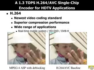
Performance Analysis of H.264 Encoder on TMS320C64x+ and ARM 9E. Nikshep Patil. Project objectives. Understand the major blocks H.264 encoder [2] Understand the Texas Instruments [16] TMS64x+ DSP architecture Understand the ARM 9E [18] DSP architecture

E N D
Performance Analysis of H.264 Encoder on TMS320C64x+ and ARM 9E NikshepPatil
Project objectives • Understand the major blocks H.264 encoder [2] • Understand the Texas Instruments [16] TMS64x+ DSP architecture • Understand the ARM 9E [18] DSP architecture • Port the H.264 encoder on the two platforms • Analyze the performance of the encoder on the two processors in terms of MIPS • Identify and optimize the most computationally expensive blocks separately for both the DSP cores • Achieve MIPS reduction of about 30%
Part 1 H.264 encoder
H.264 Encoder – Profiles [4] Seven prominent profiles – • Baseline profile • Main profile • Extended profile • High Profile • High 10 Profile • High 4:2:2 Profile • High 4:4:4 Profile
Profile structure of H.264 [3] Fig. 1. The specific coding parts of the profiles in H.264 [3]
H.264 Encoder baseline profile [4] Primarily designed for – • Low processing power platforms • Error prone transmission environments Features – • Low on coding efficiency • I- and P- slice coding • Enhanced error resilience coding such as flexible macroblock ordering (FMO) and arbitrary slice ordering (ASO) and redundant slices (RS) • Context adaptive variable length coding (CAVLC) Features not included in baseline profile – • B- slices, SI- or SP- slices • Interlace coding tools • Context adaptive binary arithmetic coding (CABAC)
Baseline profile continued[3] Major applications – • video-conferencing • mobile video streaming
Layers of H.264 encoder[7] The H.264 encoder is organized into two layers- • Network abstraction layer: Packets containing integer number of bytes with a header. • Video coding layer NAL units • Non video coding layer NAL units • Video coding layer – The coded video bitstream
Video data hierarchy [4] • Video data organized as - Picture ---> Slices ---> Macroblocks ---> Sub-macroblocks ---> Blocks ---> Pixels • Pixel is the most basic building block of a digital image
H.264 Encoder block diagram Fig. 2. The block diagram of H.264 encoder [3]
Encoding process The major encoding steps are – • Intra prediction • Inter prediction • Transform and quantization • Entropy coding • Deblocking filter
Intra prediction • Performed in pixel-domain • Prediction of pixel values as linear interpolations of pixels from the adjacent edges of neighboring macroblocks already decoded • For luma samples, the prediction block may be formed for each 4X4 subblock, each 8X8 block, or for a 16X16 macroblock • 9 directional prediction modes for each 4X4 and 8X8 luma blocks • 4 directional prediction modes for 16X16 luma block • 4 directional prediction modes for chroma blocks
Inter prediction • Generates a predicted version of a rectangular array of pixels, by choosing another similarly sized rectangular array of pixels from a previously decoded reference picture • Macroblocks partitioned into smaller sub-blocks. A large partition size is appropriate for homogeneous areas of the frame and a small partition size is beneficial for detailed areas. • A 16X16 macroblock can be partitioned in four ways: 16X16, 16X8, 8X16 or 8X8 • the 8X8 sub-block can be partitioned in four ways: 8X8, 8X4, 4X8 or 4X4
Inter prediction – Macroblock and sub macroblock partitions [3]
Sub-pixel motion compensation • Sub-pixel motion compensation provides significantly better compression performance than integer-pixel compensation • Increases complexity. • Increases coding efficiency at high bitrates and high video resolutions • For luma component, sub-pixel samples at half pixel positions are generated first and are interpolated from neighboring integer pixel samples using a 6-tap FIR filter with weights (1, -5, 20, 20, -5, 1)/32 • Quarter-pixel samples produced using bilinear interpolation between neighboring half- or integer-pixel samples • For the 4:2:0 video format, 1/8 pixel samples are required for the chroma component. These samples are linearly interpolated between integer-pixel chroma samples
Integer transform • This residual signal with spatial redundancy is split into 4X4 or 8X8 blocks. The 4X4 transform removes the need for multiplications • Hierarchical transform structure • The 4X4 blocks are first transformed with integer DCT operation. Then the DC coefficients of neighboring 4X4 transforms for the luma blocks are grouped into 4X4 blocks and transformed again by Hadamard transform • A 4X4 Walsh Hadamard transform is used for luma DC coefficients for 16X16 Intra-mode. • A 2X2 Walsh Hadamard transform is used for chroma DC coefficients.
Quantization • The quantized signal Y is obtained from the input signal X using the relation – Y = X . ROUND(SF/Qstep) -X is the input signal -Y is the output signal -Qstep is the quantization parameter • The quantization parameter varies from 0 to 51 allowing a total of 52 quantization steps • The scaling operations for the quantization step sizes are arranged with logarithmic step size increments. An increment of Qstep by 6 corresponds to doubling of quantization step size
Entropy coding • The syntax elements other than the residual data are encoded by the Exp-Golomb codes • A more sophistical method - CAVLC - employed for coding the residual data • In CAVLC inter-symbol redundancies are exploited by switching VLC tables for various syntax elements depending on already transmitted coding symbols • The increased adaptivity allows improved coding in comparison to schemes using a single VLC table • However, symbol probabilities greater than 0.5 are not handled efficiently. This may prevent usage of symbols with a smaller alphabet size for coding of residual data
Deblocking filter Two major sources that can introduce blocking artifacts in H.264 – • The block-based transform in intra and inter-prediction coding, and the coarse quantization of the transform coefficients. • The motion compensated prediction loop
Deblocking filter continued • The deblocking filter reduces the blocking artifacts in the block boundary. • The lumadeblocking filter process performed on four 16-sample edges • The chromadeblocking filter process performed on two 8-sample edges.
Deblocking filter: Boundaries to be filtered in a MB (Luma – solid line, Chroma– dotted line) [3]
Part 2 Digital signal processors
TI TMS320C64x+ DSP [9] • 32 bit DSP engine • The C64x+ uses an advanced very long instruction word (VLIW) architecture called VelociTI.2 • The architecture uses parallelism. It contains multiple execution units running in parallel, which allow them to perform multiple instructions in a single clock cycle • Available up to 1.1 GHz clock speeds The Major blocks of the C64x+ CPU - • Two general-purpose register files (A and B) • Eight functional units (.L1, .L2, .S1, .S2, .M1, .M2, .D1, and .D2) • Two load-from-memory data paths (LD1 and LD2) • Two store-to-memory data paths (ST1 and ST2) • Two data address paths (DA1 and DA2) • Two register file data cross paths (1X and 2X)
C64x+ CPU Fig. 3. The major functional units of the TMS320C64x+ processor [9]
C64x+ pipeline [10] The pipeline phases are divided into three stages: • Fetch • Decode • Execute The fetch phases of the pipeline are: • PG: Program address generate • PS: Program address send • PW: Program access ready wait • PR: Program fetch packet receive The decode phases of the pipeline are: • DP: Instruction dispatch • DC: Instruction decode The execute portion of the pipeline is subdivided into five phases - E1 , E2, E3, E4, E5 Different instructions require different number of execute phases to complete
ARM 9 DSP [14] • 32 bit reduced instruction set computer (RISC) processor • RISC architecture provides fixed length instructions that can each execute in a single cycle. In contrast, in complex instruction set computer (CISC) processors the instructions are often of variable size and take many cycles to execute • Uses load – store architecture
ARM 9E CPU Fig. 4. The ARM 9E processor architecture [14]
Major blocks of ARM 9E CPU • Instruction decoder deciphers the incoming instruction. • The sign extend hardware converts signed 8-bit and 16-bit numbers to 32-bit values as they are read from memory and placed in a register. • Data items are placed in the register file—a storage bank made up of 32-bit registers. Since the ARM core is a 32-bit processor, most instructions treat the registers as holding signed or unsigned 32-bit values. • One important feature of the ARM is that the second operand can alternatively be preprocessed in the barrel shifter before it enters the ALU. Together the barrel shifter and ALU can calculate a wide range of expressions and addresses. • The ALU (arithmetic logic unit) or MAC (multiply-accumulate unit) takes the register values from the A and B buses and computes a result • For load and store instructions the incrementer updates the address register before the core reads or writes the next register value from or to the next sequential memory location.
Register functionalities • Register r0 to r12 are general purpose scratch registers. • Register r13 is traditionally used as the stack pointer (sp) and stores the head of the stack in the current processor mode. • Register r14 is called the link register (lr) and this is where the core puts the return address whenever it calls a subroutine. • Register r15 is the program counter (pc) and contains the address of the next instruction to be fetched by the processor.
ARM 9E pipeline [14] ARM 9E uses a 5 stage pipeline – -Fetch -Decode -Execute -Data memory access -Register write
Part 3 Implementation and Optimization
Implementation Three algorithms are implemented on the processors • FIR filter • Fast fourier transform • Discrete cosine transform
Optimization • The DSP implementations need to be optimized to reduce cycle consumption • Lesser number of cycles translates lesser power consumed for battery powered devices such as mobile devices • DSP algorithm optimization is a multi step process. The C programming language level and assembly level optimization techniques are discussed next
Optimization: C level [27] The most common optimization techniques at the C level are – • Loop unrolling • Using intrinsics • Inlining functions • Avoiding conditional statements in the loop • Implementing all the basicops in intrinsics • Replacing multiply with shifts
Optimization: Assembly level [14] The optimization techniques used here are - • Instruction scheduling: Reordering the instructions in a code sequence to avoid processor stalls • Register allocation: Deciding how variables should be allocated to ARM registers or stack locations for maximum performance • Conditional execution: Accessing the full range of ARM condition codes and conditional instructions
Results • In the first phase of implementation a simple FIR filter is implemented on both the DSPs gaining useful insight into the processor architectures and assembly coding. • In the next phase the fast fourier transform (FFT) and discrete cosine transform (DCT) are implemented on the DSPs. • The C source codes and the assembly codes are provided separately for all three functions. • The results produced by the DSPs have been verified using MATLAB.
Conclusion • DSP is a two step process, first, the need to convert mathematical theory into an algorithm and second is to convert algorithm to implementation. • The focus of this project has been the latter. Here we focus on the implementation of DSP algorithms on the ARM 9E and C64x+ platforms. • Presently, the processor architectures and DSP algorithm implementation process is explored with the implementations of FIR Filter, FFT and DCT applications. • The continuing work will focus on the implementation of the full H.264 baseline profile encoder on the two DSPs
List of acronyms in alphabetical order • ARM – Advanced RISC Machine • ASO - Arbitrary slice ordering • AVC – Advanced video coding • CABAC – Context adaptive binary arithmetic coding • CAVLC - Context adaptive variable length coding • CCS – Code composer studio • CISC – Complex instruction set computer • DCT – Discrete cosine transform • DSP –Digital signal processor • FFT – Fast fourier transform • FIR – Finite impulse response
List of acronyms in alphabetical order continued • FMO - Flexible macroblock ordering • ITU -T -International Telecommunication Union—Telecommunication sector • JM – Joint model • MPEG – Moving Picture Experts Group • NAL - Network abstraction layer • RISC – Reduced instruction set computer • RS - Redundant slices • RVDS – Real view developer suite • TI – Texas Instruments • VCEG - Video Coding Experts Group • VCL – Video coding layer • VLIW - Very long instruction word
References [1]. H.264/AVC JM software: http://iphome.hhi.de/suehring/tml/ [2]. H.264: International Telecommunication Union, Recommendation ITU-T H.264: Advanced Video Coding for Generic Audiovisual Services, ITU-T, 200 [3]. Soon-kak Kwon et al. “Overview of H.264 / MPEG-4 Part 10 (pp.186-216)”, Special issue on “Emerging H.264/AVC video coding standard”, J. Visual Communication and Image Representation, vol. 17, pp.183-552, April 2006 [4].A.Puri et al. “Video coding using the H.264/MPEG-4 AVC compression standard”, Signal Processing: Image Communication, vol.19, pp 793-849, Oct 2004 [5].G.NageswaraRao et al. “Real-Time Software Implementation of H.264 Baseline Profile Video Encoder for Mobile and Handheld Devices” - Emuzed India Pvt. Ltd, Bangalore, India [6]. T. Weigand et al. “Overview of the H.264/AVC Video Coding Standard,” IEEE Transactions on Circuits and System for Video Technology, vol.13, no.7, pp.560-576, July 2003
References continued [7]. Heiko Schwarz et. al. “Overview of the Scalable Video Coding Extension of the H.264/AVC Standard”, IEEE Transactions on circuits and systems for video technology, vol. 17, no. 9, September 2007 [8]. An overview of the H.264 encoder: www.vcodex.com [9]. TMS320C64x/C64x+ DSP CPU and instruction set reference guide: http://focus.ti.com/lit/ug/spru732h/spru732h.pdf [10].Technical reference manual TMSC320C64x+: http://focus.ti.com/lit/ug/spru395b/spru395b.pdf [11].TMS320C6000 assembly language tools v6.1 user's guide: http://focus.ti.com/lit/ug/spru186q/spru186q.pdf [12]. Code composer studio development tools v3.3 getting started guide: http://focus.ti.com/lit/ug/spru509h/spru509h.pdf