Download
1 / 35
420 likes | 1.47k Vues
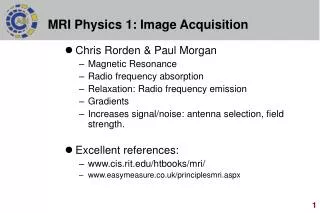
MRI Physics 1: Image Acquisition. Chris Rorden & Paul Morgan Magnetic Resonance Radio frequency absorption Relaxation: Radio frequency emission Gradients Increases signal/noise: antenna selection, field strength. Excellent references: www.cis.rit.edu/htbooks/mri/

E N D
MRI Physics 1: Image Acquisition • Chris Rorden & Paul Morgan • Magnetic Resonance • Radio frequency absorption • Relaxation: Radio frequency emission • Gradients • Increases signal/noise: antenna selection, field strength. • Excellent references: • www.cis.rit.edu/htbooks/mri/ • www.easymeasure.co.uk/principlesmri.aspx
Units of magnetic strength • Tesla and Gauss are measures of magnetic field strength • Earth’s magnetic field ~0.5 Gauss. • 1Tesla = 10,000 Gauss. • Our fMRI system is 3T. ~x60,000 earth’s field strength
Anatomy of an atom • Atoms are the building blocks of our world. • Composed of 3 components • Electrons: tiny negatively charged particles. • Protons: heavy positively charged particles. • Neutrons: heavy particles without charge. • Electrons are often thought of like planets: tiny objects distantly orbiting a massive core. • Neutrons and protons form the dense nucleus of an atom.
Atomic Nuclei • Atomic nuclei are composed of protons and neutrons. • The number of protons determines the element, e.g. hydrogen has one proton, helium has two. • The number of neutrons determines the isotope. • Most helium has two neutrons: 4He. • Some helium atoms only have one neutron: 3He. • Most hydrogen has no neutrons: 1H. • Deuterium (2H) is found in ‘heavy’ water, Tritium (3H) is radioactive (spontaneous decay) and is used to enhance nuclear bombs. 4He 3He 1H 2H
Nuclear Magnetic Resonance • Felix Block and Edward Purcell • 1946: the nuclei of some elements absorb and re-emit radio frequency energy when in magnetic field • 1952: Nobel prize in physics • Atoms with odd number of protons/neutrons spin in a magnetic field • Nuclear: properties of nuclei of atoms • Magnetic: magnetic field required • Resonance: interaction between magnetic field and radio frequency Bloch Purcell
How fast do hydrogen atoms spin? 180 The rate of rotation is determined by the strength of the magnetic field. Larmor equation f = B0 For Hydrogen, = 42.58 MHz/T At 1.5T, f = 63.76 MHz At 3T, f = 127.7 MHz Resonance Frequency (MHz) 40 1.0 4.0 Field Strength (Tesla)
Radiofrequency Pulses • A radiofrequency (RF) pulse at the Larmor frequency will be absorbed. • This higher energy state tips the spin, so it is no longer aligned to the field. • An RF pulse at any other frequency will not influence the nuclei. • This is resonance.
Source of MR signal • At rest, atoms align parallel to magnetic field. • Lowest energy state. • After RF absorption, net magnetization is orthogonal to magnetic field • RF emission at larmor frequency • RF emission decays with time
Absorption and Relaxation • Our RF transmission is absorbed by atoms at Larmor frequency. • After the RF pulse, atoms will begin to realign with the magnetic field: relaxation • During this period, an RF signal is emitted. • This signal will be at the Larmor frequency. • An antenna can measure this signal.
MRI compass analogy N • Compass needle points North • Briefly tap magnet: needle no longer points North • Wait, needle returns to North (lower energy state) N N
Hydrogen is the mainstay for MRI • We will focus on Hydrogen • Hydrogen abundant in body (63% of atoms). • Elements with even numbers of neutrons and protons have no spin, so we can not image them (4He, 12C). • 23Na and 31P are relatively abundant, so can be imaged. • Larmor frequency varies for elements: • 1H = 42.58 Mhz/T • 13C = 10.7 Mhz/T • 19F = 40.1 Mhz/T • 31P = 17.7 Mhz/T • Therefore, by sending in a RF pulse at a specific frequency we can selectively energize hydrogen.
Electromagnetic Spectrum • MRI signals are in the same range as FM radio and TV (30-300MHz). • MRI frequency is non-ionizing radiation, unlike X-rays. • Absorbed RF will cause heating. • Specific absorption rate (SAR): measure of the energy absorbed by tissue. • Increases ~ with square of field strength. • Higher SAR = more energy = more signal = more heating • FDA limits SAR, and is a limiting factor for some protocols (3 W/kg averaged over 10 minutes). Ionizing Radiation Breaks Bonds Non-Ionizing Radiation Heating Excites Electrons Excites Nuclei
Making a spatial image • To create spatial images, we need a way to cause different locations in the scanner to generate different signals. • To do this, we apply gradients. • Gradients make the magnetic field slightly stronger at one location compared to another. • Lauterbur: first MRI: 2003 Nobel Prize. Lauterbur
128 Mhz 127 Mhz 126 Mhz Slice Selection Gradient • Gradients make field stronger at one location compared to another. • Larmor frequency different along this dimension. • RF pulse only energizes slice where field strength matches Larmor frequency. Field Strength Z Position
Slice Selection Gradient • Gradual slice selection gradients will select thick slices, while steep gradients select thinner slices. • The strength of your scanner’s gradients can limit minimum slice thickness. • FDA limits speed of gradient shift (dB/dt) and some of our protocols can elicit slight tingling sensation or a brief muscle twitches. • Position of gradient determines which 2D slice is selected. Field Strength Field Strength Field Strength Field Strength Z Position Z Position Z Position Z Position
Phase encoding gradient • Orthogonal gradient applied between RF pulse and readout • This adjusts the phase along this dimension. • Analogy: Phase encoding is like making timezones. Clocks in different zones will have different phases. Y Position Field Strength
Frequency encoding gradient • Apply final orthogonal gradient when we wish to acquire image. • Slice will emit signal at Lamour frequency, e.g. lines at higher fields will have higher frequency signals. • Aka ‘Readout gradient’. X Position Field Strength
Raw MRI image: K-Space Raw image is 2D Frequency Map. Apply Fourier Transform to reconstruct image. Source: Traveler’s Guide to K-space (C.A. Mistretta)
Reconstruction • Medical scanners automatically reconstruct your data. • You can manually reconstruct data using Tokarczuk’s free Intel Reconstruction Tool: www.mricro.com/import.html • Fourier Transforms are slow: 1021-sample data requires >2 million multiplications (2*N2) • Fast Fourier Transform: 1024-sample data requires 20,000 multiplications. (2(N log N)) • Optimal when data is power of two (64,128,256, 512), reverts to traditional Fourier for prime numbers • This is why most image matrices are a power of 2.
MRI scanner anatomy • A helium-cooled superconducting magnet generates the static field. • Always on: only quench field in emergency. • niobium titanium wire. • Coils allow us to • Make static field homogenous (shims: solenoid coils) • Briefly adjust magnetic field (gradients: solenoid coils) • Transmit, record RF signal (RF coils: antennas)
MRI scanner anatomy Antennas Magnet Gradient RF Transmit RF Receive
EPI • In conventional MRI, we collect one line of our matrix with each RF pulse. • So a 64x64 matrix with a TR of 2sec will be generated in 128 seconds. • Problem: this is unacceptable if the object changes rapidly: • Images of the heart: shape changes quickly, conventional image would be blurred. • Imaging brain activity: could not see changes that occur within a few seconds. • Echo Planar Imaging: By rapidly applying the frequency gradient, we can collect a 2D slab with a single RF pulse.
Echo Planar Imaging • EPI was devised in 1977 by Sir Mansfield. • 2003 Nobel Prize. • EPI remains the principle technique for fMRI acquisition. • Alternative is ‘spiral’ imaging. • EPI does have a cost: • Image warping due to slow encoding. Mansfield EPI Multi-shot www.fmrib.ox.ac.uk/~karla/
MRI terminology • Orientation: typically coronal, sagittal or axial, can be in-between these (oblique) • Matrix Size: • Voxels in each dimension • Field of view: • Spatial extent of each dimension. • Resolution: • FOV/Matrix size. Axial Orientation 64x64 Matrix 192x192mm FOV 3x3mm Resolution Sagittal Orientation 256x256 Matrix 256x256mm FOV 1x1mm Resolution
Volumes • 3D volumes are composed of stacks of 2D slices, like a loaf of bread. • Each slice has a thickness. • Thicker slices have more hydrogen, so more signal • Volume of 1x1x1mm voxel is 1mm3 • Volume of 1x1x2mm voxel is 2mm3 • Thinner slices provide higher resolution. • Optional: gap between slices. • Reduces RF interference • Allows fewer slices to cover whole brain. 1mm Gap 2mm Thick 3mm
Creating 3D volumes from 2D EPI • Slices can be either collected sequentially (e.g. ascending axial slices) or in interleaved order (e.g. collect all odd slices, then all even slices). Sequential Interleaved … … TR TR
Slice 4 Slice 3 Slice 2 Slice 1 Sequential vs Interleaved Volumes • Interleaving reduces interference between slices. Useful if thin gap between slices. • Unfortunately, any head movements will cause worse ‘spin history’ effects for interleaved slices than sequential. (TR will be shorter for regions that were previously in another slice). • You must know slice order if you want to ‘slice time correct’ data (temporal processing lecture). Slice 4 Slice 4 Slice 3 Slice 3 Slice 2 Slice 2 Slice 1 Slice 1
Signal to Noise • Signal To noise is given by the formula VN • Where V is the volume and N is the number of samples averaged (referred to as ‘Nex’, as in ‘number of excitations’). • For example, to get the same SNR as a single 3x3x3mm scan (27mm3) we would need to collect 12 2x2x2mm (8mm3) scans or 768 1x1x1mm (1mm3) scans.
www.fmrib.ox.ac.uk/~karla/ Signal to Noise: Antennas • The MRI antenna is called a coil. • We use different coils for different body parts. • For brains, the most common antenna is the head coil, which is a volume coil: it shows the whole brain. • We can also use a surface coil: it gives great signal for a small field of view. Head coil Surface coil Volume coil Surface coil
Parallel Imaging (SENSE, iPat) • Parallel imaging uses multiple surface coils to generate a volume image. • Dramatically reduces spatial distortion and increases signal. • Optionally, you can acquire images more rapidly by only collecting a portion of k-space. • SENSE R=2 collects half of the lines. • SENSE R=3 collects one third • Reduces spatial distortion and increases speed of acquisition. Some loss in signal. 8-channel array
Parallel Imaging (SENSE, iPat) • Increasing SENSE reduction factor decreases acquisition time and spatial distortion, but high values lead to reduced signal. Effects of SENSE factor (R) on EPI R=1 R=2 R=3
Signal and Field Strength • Outside magnetic field • Spins randomly oriented • In magnetic field: • Spins tend to align parallel or anti-parallel to magnetic field. • At room temperature, ~4 parts per million more protons per Tesla align with versus against field. • As field strength increases, there is a bigger energy difference between parallel and anti-parallel alignment (faster rotation = more energy). • A larger proportion will align parallel to field. • More energy will be released as nuclei align. • Therefore, MR signal increases with square of field strength.
Signal and Field Strength • Most clinical MRI 1.5T • Our fMRI systems: 3.0T • Maximum for NbTi MRI ~9.4T • World record for superconductive MRI ~22T (Nb3Sn) • Field strength influences: • Faster Larmor frequency : • Bigger energy difference between parallel and anti-parallel alignment • Larger ratio of nuclei aligned = more signal • More signal as nuclei realign. • Reduced TR and TE: less time to take images (next week).
Signal and Field Strength • In theory: • Signal increases with square of field strength • Noise increases linearly with field strength • A 3T scanner should have twice SNR of 1.5T scanner; 7T should have ~4.7 times SNR of 1.5T. • Unfortunately, physiological artifacts also increase, so advantage is less in practice. • Benefits: speed, resolution • Costs: Artifacts, Money, SAR, wavelength effects, auditory noise
Magnetic attraction • Force in magnetic field (1.8T, unit dynes) • Water: -22 • Copper: -2.6 • Copper Chloride: +280 • Iron: +400,000 • Diamagnetic material repelled (e.g. H2O). • Paramagnetic material attracted (e.g. CuCl, Gd). • Ferromagnetic material strongly attracted (Fe). • Even without magnetic field, magnetic moments aligned • Dangerous near MRI scanner