Download

1 / 65
680 likes | 895 Vues
Design and drawing of RC Structures CV61. Dr. G.S.Suresh Civil Engineering Department The National Institute of Engineering Mysore-570 008 Mob: 9342188467. Email: gss_nie@yahoo.com. WATER TANKS . Learning out Come. DESIGN OF RECTANGULAR WATER TANK RESTING ON GROUND WITH RIGID BASE

E N D
Design and drawing of RC StructuresCV61 Dr. G.S.Suresh Civil Engineering Department The National Institute of Engineering Mysore-570 008 Mob: 9342188467 Email: gss_nie@yahoo.com
Learning out Come • DESIGN OF RECTANGULAR WATER TANK RESTING ON GROUND WITH RIGID BASE • REVISION
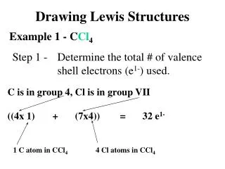
Introduction • Design a rectangular water tank 5m x 4m with depth of storage 3m, resting on ground and whose walls are rigidly joined at vertical and horizontal edges. Assume M20 concrete and Fe415 grade steel. Sketch the details of reinforcement in the tank
Step1: Analysis for moment and tensile force E A C Free a=H=3m F Fixed b=4m B D L=5m
Step1: Analysis for moment and tensile force i) Long wall:
Step4: Design for Horizontal moment • Horizontal moments at the corner in long and short wall produce unbalanced moment at the joint. This unbalanced moment has to be distributed to get balanced moment using moment distribution method.
Step5: Base Slab • The slab is resting on firm ground. Hence nominal thickness and reinforcement is provided. The thickness of slab is assumed to be 200 mm and 0.24% reinforcement is provided in the form of #8 @ 200 c/c. at top and bottom • A haunch of 150 x 150 x 150 mm size is provided at all corners
Dr.G.S.Suresh 1. LAYOUT DRAWING
Dr.G.S.Suresh Introduction • Drawing is the language of engineers • Structural drawings guide builders in the construction • The guidelines given in IS 962 and SP 34 • Drawings are prepared in different sizes • In large projects, the structural drawings are of same size
Introduction (Contd.) PAPER SIZE Dr.G.S.Suresh
Dr.G.S.Suresh • Layout of Structural Drawing
Dr.G.S.Suresh • Scale: Plan:- 1:100, 1:50 Elevation:- 1:5, 1:30 Sections:- 1:50, 1:30, 1:25, 1:20,1:15,1:10
Dr.G.S.Suresh Structural Lay-Out Drawing • Positioning and orientation of columns • Positioning of beams • Spanning of slabs • Layout of stairs • Selecting proper type of footing
Dr.G.S.Suresh Structural Lay-Out Drawing • Two axes marked one side with alphabets and the other with numbers. • Columns are marked at the intersection of grids • Beams are marked using two parallel lines • Slabs are indicated either as one way or two way
Dr.G.S.Suresh Structural Lay-Out Drawing: Column & Footing A B C D 1 2 3 4
Dr.G.S.Suresh Structural Lay-Out Drawing
Dr.G.S.Suresh Structural Lay-Out Drawing A B C D 1 2 3 4
Dr.G.S.Suresh Structural Lay-Out Drawing
Dr.G.S.Suresh Introduction • Carries Transverse External Loads That Cause Bending Moment, Shear Forces And In Some Cases Torsion • Concrete is strong in compression and very weak in tension. • Steel reinforcement is used to take up tensile stresses in reinforced concrete beams. • Mild steel bars or Deformed or High yield strength deformed bars (HYSD) • HYSD bars have ribs on the surface and this increases the bond strength at least by 40%
Specification for the reinforcement in beams is given in clause 8.1 to 8.6 of SP34