Download
1 / 103
1.22k likes | 1.91k Vues
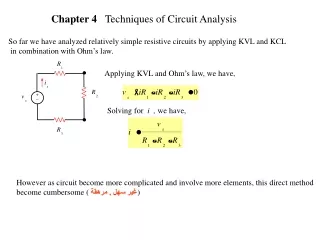
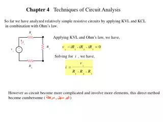
Chapter 4 Techniques of Circuit Analysis. So far we have analyzed relatively simple resistive circuits by applying KVL and KCL in combination with Ohm’s law. Applying KVL and Ohm’s law, we have,. Solving for i , we have,.

E N D
Chapter 4 Techniques of Circuit Analysis So far we have analyzed relatively simple resistive circuits by applying KVL and KCL in combination with Ohm’s law. Applying KVL and Ohm’s law, we have, Solving for i , we have, However as circuit become more complicated and involve more elements, this direct method become cumbersome ( غير سهل , مرهقة)
However as circuit become more complicated and involve more elements, this direct method become cumbersome ( غير سهل , مرهقة) In this chapter we introduce two powerful techniques of circuit analysis that aid in the analysis of complex circuit which they are known as Node-Voltage Methodor Nodal Analysis Mesh-Current Method or Mesh Analysis In addition to these method we will develop other method such as source transformations, Thevenin and Norton equivalent circuit.
4.1 Terminology Planar Circuit : a circuit that can be drawn on a plane with no crossing branches as shown The circuit shown can be redrawn which is equivalent to the above circuit Planar Circuit
The circuit shown is non planar circuit because it can not be redrawn to make it planar the circuit
Describing a Circuit – The vocabulary Consider the following circuit A point where two or more circuit elements join a Node A node where three or more circuit elements join b Essential node path A trace of adjoining basic elements with no elements included branch A path that connects two nodes Essential branch A path that connects two essential nodes without passing through an essential node loop A path whose last node is the same as the starting node mesh A loop that does not enclose any other loops Planar Circuit A circuit that can be drawn on a plane with no crossing branches
(a) All nodes ? The nodes are a, b, c, d, e, f and g
(b) The essential nodes ? A node where three or more circuit elements join The essential nodes are b, c, e and g
(c) All branches ? A path that connects two nodes The branches are
(d) All essential branches ? A path that connects two essential nodes without passing through an essential node The essential branches are
(e) All meshes ? The meshes are
(f) Two paths that are not loops or essential branches ? is a paths , but it is not a loop because it does not have the same starting and ending nodes Nor is it an essential branch because it does not connect two essential nodes Is a paths that are not loop or essential branches ?
(g) Two loops that are not meshes ? is a loop , but it is not a mesh because there are two loops within it is a loop , but it is not a mesh because there are two loops within it
Simultaneous Equations- How many Let the circuit as shown There are nine branches in which the current is unknown Note that the current I is known
Since there are nine unknown current Therefore we need nine independent equations There will be 6 independent KCL equations since the 7th one can be written in terms of the 6 equations Since there are 7 nodes We still need 3 more equations They will come fromKVL around three meshes orloops Note the meshe orloop we apply KVL around should not contain the current sourceI since we do not know the voltage across it
Since KCL at the non essential (connecting two circuit elements only) like a , d , f will have the following results Therefore we have 6currents and 4 essential nodes (connecting three or more circuit elements) like b, c, e, g
Therefore Applying KCL to 3 of the 4essential nodes since KCL on the 4th node will have an equation that is not independent but rather can be derived from the 3KCL equations Applying KCL to the essential nodes b, c, and e ( we could have selected any three essential nodes) we have KCL at node bwe have KCL at node cwe have KCL at node ewe have Which is a linear combination of the other KCL’s Note applying KCL on node g
Therefore the remaining 3 equations will be derived from KVL around 3meshes Since there are 4 meshes only, we will use the three meshes with out the current source KVL around mesh 1 KVL around mesh 2 KVL around mesh 2
KCL Equations 6 equations and 6 unknown which can be solved for the currents KVL Equations
4.2 Node-Voltage Method Nodal analysis provide a general procedure for analyzing circuits using node voltages as the circuit variables Node-Voltage Method is applicable to both planar and nonplanar circuits Using the circuit shown, we can summarize the node-voltage methods as shown next :
1 2 3 3 Step 1identify all essentials nodes Do not select the non essentials nodes Step 2select one of the essentials nodes ( 1, 2, or 3) as a reference node Although the choice is arbitrary the choice for the reference node is were most of branches, example node 3 Selecting the reference node will become apparent as you gain experience using this method (i,.e, solving problems)
v1 v2 A node voltage is defined as the voltage rise from the reference node to a nonreference node Step 3label all nonrefrence essentials nodes with alphabetical label as v1, v2… Step 4write KCL equation on all labels nonrefrence nodes as shown next
v1 v2 i1 i2 i3 KCL at node 1 + + = Let us find , , By applying KVL KVL on the middle mesh, we have similarly
v1 v2 10 i1 i2 i3 Therefore + + = We have + + = If we look at this KCL equation, we see that the current we notice that the potential at the left side of the 1 W resistor which is tied to the + of the 10 V source is 10 V because the – is tied to the reference
v1 v2 10 i1 i2 i3 Therefore we can write KCL at node 1 without doing KVL’s as we did previously + + =
Similarly v1 v2 i1 i3 i2 + = KCL at node 2
v1 v2 10 + + = + = Two equations and two unknowns namely v1 , v2we can solveand have
4.3 TheNode-Voltage Method and Dependent Sources If the circuit contains dependent source, the node-voltage equations must be supplemented with the constraint equations imposed by the dependent source as will be shown in the example next Example 4.3 Use the node voltage method to find the power dissipated in the 5 W resistor
1 2 3 3 The circuit has three essentials nodes 1, 2, and 3 and one of them will be thereference We select node 3 as the reference node since it has the most branches (i.e, 4 branches) We need two node-voltage equations to describe the circuit
20 v1 v2 The circuit has two non essentials nodes which are connected to voltage sources and will impose the constrain imposed by the value of the voltage sources on the non essential nodes voltage Applying KCL at node 1 Applying KCL at node 2
20 v1 v2 The second node equation contain the current ifwhich is related to the nodes voltages as Substituting in the second node equation, we have the following nodes equations Solving we have
4.4 TheNode-Voltage Method : Some Special Cases Let us consider the following circuit 1 2 3 3 The circuit has three essentials nodes 1, 2, and 3 which means that two simultaneous equations are needed. From the three essentials nodes, areference node has been chosen and the other two nodes have been labeled
v1 v2 100 However since the 100 V source constrains the voltage between node 1 and the referencenode to 100 V. This mean that there is only one unknown node voltage namely (v2) Applying KCL at node 2 Since Knowing v1andv2 we can calculate the current in every branch
Nodal Analysis with voltage sources Some Special Cases This voltage source is connected between non reference and reference
This voltage source is connected between two non reference nodes reference
Enclose the voltage source in a region called supper node Apply KCL to that region
KCL on the Supper node The second equation come from the constraint on the voltage source Two equations and two unknowns , we can solve
Two voltage sources are connected between two non reference nodes reference
supper node apply as will to dependent sources Dependent Voltage source
4.5 Introduction to the Mesh-Current Method Consider the following planar circuit There are 4 essentials nodes
There are 7 essentials branches were the current is unknown Therefore to solve via the mesh-current method we must write 4mesh -current
A mesh current is the current that exists only in the perimeter of a mesh as shown in the circuit below The mesh current satisfy Kirchhoff’s Current Law (KCL) At any node in the circuit, a given mesh current both enters and leaves the node Mesh current is not always equal branch current