Download
1 / 1
10 likes | 206 Vues
PC. Amp. Network Analiser. Control Unit. Dr. Thomas Börner Deutsches Zentrum für Luft- und Raumfahrt e.V. (DLR) Institut für Hochfrequenztechnik und Radarsysteme P.O.-Box 1116, D-82230 Weßling, Germany Phone/Fax: +49-8153-28-2368 / -1449, Email: Thomas.Boerner@dlr.de.

E N D
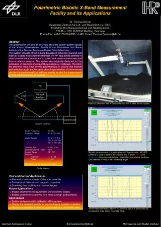
PC Amp Network Analiser Control Unit Dr. Thomas Börner Deutsches Zentrum für Luft- und Raumfahrt e.V. (DLR) Institut für Hochfrequenztechnik und Radarsysteme P.O.-Box 1116, D-82230 Weßling, Germany Phone/Fax: +49-8153-28-2368 / -1449, Email: Thomas.Boerner@dlr.de Polarimetric Bistatic X-Band Measurement Facility and its Applications Abstract The presentation will give an overview about the current system design of the X-band Measurement Facility of the Microwaves and Radar Institute of the German Aerospace Center Oberpfaffenhofen. The system consists of two X-band broadband antennas (transmit and receive) located in an anechoic chamber. An HP-VEE based software is used to move the antennas and to collect and store the measured data from a network analyser. The system was originally designed for the estimation of dielectric and magnetic properties of materials. Therefore the antennas have been moved synchronically to assure that incident and reflection angle are the same. Also the polarisation of the antennas can be changed manually at arbitrary angles so that the measurement of a full scattering matrix is possible. Anechoic chamber, two X-Band antennas and a table for the targets. System scheme Center Frequency: 9.6 GHz Frequency Range: 8.2 to 12.4 GHz Useful Ranges: 9.4 to 11.7 GHz 12.3 to 12.9 GHz 13.4 to 14.7 GHz Chamber Size: 2.7m 2.1m Distance Antenna - Table: 1.2m Angular Range: 12° - 70° Accuracy: - Amplitude ~ 0.1 dB - Phase ~ 0.5° Polarisation can be adjusted manually! Bistatic measurement of a metal plate in VV polarisaton. HP-VEE software is used to control movements and to show phase and amplitude of the measured signal provided by the network analyser. One antenna is fixed to 46° incidence angle. System specs • Past and Current Applications • Attenuation measurements of absorber materials. • Estimation of dielectric and magnetic properties. • Scattering from multi-layered dieletric targets. • Future Applications • Bistatic polarimetric measurements using canonic targets. • Bistatic polarimetric scattering from moist & rough soils/surfaces. • Open Issues • Bistatic and polarimetric calibration of the system. • Theory and coherent models for canonic targets (partially available). • Theory and coherent models for rough surfaces in the bistatic case. Same measurement as above, but now the signal is attenuated by an absorber plate above the metal plate.