Download
1 / 38
470 likes | 905 Vues
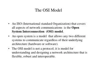
Semester 1 Chapter 2 The OSI Model. The OSI Reference Model. The OSI layer was introduced by the International Organization for Standardization (ISO) in 1984 in order to provide a reference model to make sure products of different vendors would interoperate in networks.

E N D
Semester 1 Chapter 2 The OSI Model
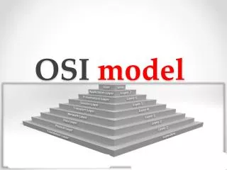
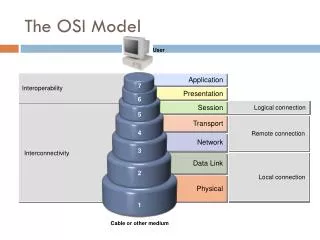
The OSI Reference Model • The OSI layer was introduced by the International Organization for Standardization (ISO) in 1984 in order to provide a reference model to make sure products of different vendors would interoperate in networks. • OSI is short for Open Systems Interconnection. • The OSI layer shows WHAT needs to be done to send data from an application on one computer, trough a network, to an application on another computer, not HOW it should be done. • A layer in the OSI model communicates with three other layers: the layer above it, the layer below it, and the same layer at its communication partner. • Data transmitted between software programs passes all 7 OSI layers. • The Application, Presentation and Session layers are also known as the Upper Layers. • The Data Link and Physical layers are often implemented together to define LAN and WAN specifications.
What is a Protocol? • A Protocol is a set of rules that make communication on a network more efficient. • E.G. - When answering the telephone, someone says, "Hello," then the person calling says, "Hello. This is.... "; and so it goes back and forth • One technical definition of a data communications protocol is: a set of rules, or an agreement, that determines the format and transmission of data. Layer n on one computer communicates with Layer n on another computer.
Remembering the OSI Model • All 7 - Application • People 6 - Presentation • Seem 5 - Session • To 4 - Transport • Need 3 - Network • Domino’s 2 - Data Link • Pizza 1 - Physical
Remembering the OSI Model • Away 7 - Application • Pizza 6 - Presentation • Sausage 5 - Session • Throw 4 - Transport • Not 3 - Network • Do 2 - Data Link • Please 1 - Physical
Layer 1 – Physical Layer • The physical layer defines the electrical, mechanical, procedural, and functional specifications for activating, maintaining, and deactivating the physical link between communicating network systems. • Physical layer specifications define characteristics such as: • voltage levels • timing of voltage changes • physical data rates • maximum transmission distances • physical connectors • Physical layer implementations can be categorized as either LAN or WAN specifications. • more on next slide…
Layer 1 – Physical Layer – Continued… • Examples of LAN specifications are: • Ethernet • FastEthernet • Token Ring • FDDI • Examples of WAN specifications are: • HSSI • V.24 • V.35 • BRI • RS-232 • Transmits bits. (bitstream) • Repeaters operate at this layer.
Some Layer 1 Examples… 10 Base 2 – Co Ax 10 Base 5 – Thicknet Fibre Optic Connectors UTP
Layer 2 – Data Link Layer • Defines psychical addressing, network topology, and is also concerned with error notification, sequencing of frames and flow control. • Examples of network topologies are: • Star • Bus • Ring • Physical addresses are also known as hardware and BIA's (Burned In Addressess) but most commonly as MAC addresses. • Examples of Data Link LAN specifications are: • Ethernet • FastEthernet • Token Ring • FDDI • More on next slide…
Layer 2 – Data Link Layer – Continued… • Examples of Data Link WAN specifications are: • Frame Relay (operates also on the Physical layer) • PPP (operates also on the Physical layer) • X.25 (operates also on the Physical and Network layer) • Transmits Frames. • Bridges and Switches operate at this layer. • The Data Link layer consists of two sublayers: • LCC (Logical Link Control) sublayer • Manages communication between devices over a single link of a network. • Enables multiple higher-layer protocols to share a single physical data link. • MAC sublayer • Manages protocol access to the physical network medium. • Determines hardware addresses.
Some Layer 2 Examples… Network Interface Card (NIC) Workgroup Switch
Layer 3 – Network Layer • Defines logical addressing for nodes and networks/segments. • Enables internetworking, passing data from one network to another. • Defines the logical network layout so routers can determine how to forward packets trough an internetwork. • Routing occurs at this layer, hence Routed and Routing protocols reside on this layer. • Routed protocols are used to encapsulate data into packets. The header added by the Network layer contains a network address so it can be routed trough an internetwork. • Examples of Network layer Routed protocols are: • IP, IPX, AppleTalk • Routing protocols are used to create routing tables; routing tables are used to determine the best path / route. Routing protocols provide periodic communication between routers in an internetwork to maintain information on network links in a routing table. • Examples of Network layer Routing protocols are: • OSPF, IGRP/EIGRP, RIP, BGP. • Transmits Packets. • Routers operate at this layer.
Layer 4 – Transport Layer • The main purpose of this layers is making sure that the data is delivered error-free and in the correct sequence. • Establishes, maintains and terminates virtual circuits. • Provides error detection and recovery. • Is concerned with reliable and unreliable transport. When using a connection-oriented, reliable transport protocol, such as TCP, acknowledgments are send back to the sender to confirm that the data has been received. • Provides Flow Control and Windowing. • Provides multiplexing; the support of different flows of data to different applications on the same host. • Examples of Transport layer protocols are: • TCP (connection-oriented, reliable, provides guaranteed delivery.) • UDP (connectionless, unreliable, less overhead, reliability can be provided by the Application layer) • SPX • Transmits Segments.
Layer 5 – Session Layer • The session layer establishes, manages, maintains and terminates communication channels between software programs on network nodes. • Provides error reporting for the Application and Presentation layer. • Examples of Session layer protocols are: • NFS • SQL • RPC • Transmits Data.
Layer 6 – Presentation Layer • Defines coding and conversion functions. • Ensures that information sent from the application layer of one system is readable by the application layer of another system. • Includes common data representation formats, conversion of character representation formats, common data compression schemes, and common data encryption schemes, common examples of these formats and schemes are: • MPEG, QuickTime • ASCII, EBCDIC • GIF, TIFF, JPEG • Transmits Data.
Layer 7 – Application Layer • Provides network services directly to applications. Software programs itself are not part of the OSI model. • Determines the identity and availability of communication partners, and determines if sufficient resources are available to start program-to-program communication. • This layer is closest to the user. • Examples of Application layer protocols are: • Telnet • SMTP • FTP • SNMP • Transmits Data.
Data Encapsulation • Data Encapsulation is the process of adding a header to wrap the data that flows down the OSI model. • Each OSI layer may add it's own header to the data received from above. (from the layer above or from the software program 'above' the Application layer.) • The 5 Steps of Data Encapsulation are: • 1. The Application, Presentation andSession layers create DATA from users‘input. • 2. The Transport layer converts the DATA to SEGMENTS • 3. The Network layer converts the SEGMENTS to PACKETS (or datagrams) • 4. The Data Link layer converts the PACKETS to FRAMES • 5. The Physical layer converts the FRAMES to BITS. • At the sending computer the information goes from top to bottom while each layers divides the information received from upper layers in to smaller pieces and adds a header. At the receiving computer the information flows up the model discarding the corresponding header at each layer and putting the pieces back together.
What are PDU’s? Each layer contains a Protocol Data Unit (PDU). PDU’s are used for peer-to-peer conversations.
The TCP/IP Model • The TCP/IP Model was develop by the Department of Defense in the late 60s’ to ensure data communications would not be interrupted even under the worse circumstances. • Since then, TCP/IP has become the de facto method we use for data communications on the Internet.
Exploring the 4 Layers of the TCP/IP Model Application • Includes all the functions of the OSI’s Application, Presentation, & Session layers including: • Data representation • Data encryption and • Dialog control Transport Internet Network Access
Application Layer Protocols Application • FTP-File Transfer Protocol • HTTP-Hypertext Transfer Protocol • SMTP-Simple Mail Transfer Protocol • DNS-Domain Name Service • TFTP-Trivial File Transfer Protocol Transport Internet Network Access
Exploring the 4 Layers of the TCP/IP Model Application • Uses the TCP protocol and is responsible for quality of service issues including: • Reliability • Flow Control and • Error Correction Transport Internet Network Access
Transport Layer Protocols Application • TCP-Transmission Control Protocol • UDP-User Datagram Protocol Transport Internet Network Access
Exploring the 4 Layers of the TCP/IP Model Application • Uses the IP protocol and is responsible for: • Path determination and • Packet switching. Transport Internet Network Access
Internet Layer Protocols Application • IP – Internet Protocol Transport Internet Network Access
Exploring the 4 Layers of the TCP/IP Model Application • Includes all the functions of the OSI’s Data Link & Physical layers including: • Processes required by IP to ensure a packet reaches its destination. • All the various LAN & WAN Technologies such as 100BaseTX & Frame Relay. Transport Internet Network Access
Network Access Layer Protocols Application • LAN and WAN Technologies Transport Internet Network Access
Comparing the 2 Models TCP/IP OSI Application Application Presentation Session Transport Transport Internet Network Network Access Data Link Physical
Why are there 2 models? • TCP/IP is the most popular “protocol specific” model used on the Internet. • However, TCP/IP does not cover all the protocols and standards we will be exploring. • The OSI Model is “protocol independent.” Therefore, all topics covered in the curriculum can fit into its framework.
What should I know for the test? • The OSI Model’s layers & their key characteristics and functions. • The process of data encapsulation and the various PDUs. • The TCP/IP layers and its corresponding protocols. • Comparison of the two model’s layers.
Sample CCNA Question #1 In the TCP/IP model which layer would deal with reliability, flow control, and error correction? A – Transport Layer B – Internet Layer C – Network Layer D – Application Layer
Sample CCNA Answer #1 In the TCP/IP model which layer would deal with reliability, flow control, and error correction? A – Transport Layer B – Internet Layer C – Network Layer D – Application Layer
Sample CCNA Question #2 What is the control information called that is placed before data when encapsulating that data for network transmission? A – Frame B – Header C – Capsule D – Routing Information
Sample CCNA Answer #2 What is the control information called that is placed before data when encapsulating that data for network transmission? A – Frame B – Header C – Capsule D – Routing Information