Download
1 / 36
360 likes | 591 Vues
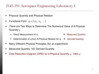
Engineering H191 Engineering Fundamentals and Laboratory I. Week 02 Day 03 Isometric Pictorials. Objectives. Projections: The Four Basic Types Creating Isometric sketches Sketching Ellipses. Orthographic Projections. Projections: Four Basic Types.

E N D
Engineering H191Engineering Fundamentals and Laboratory I Week 02 Day 03 Isometric Pictorials
Objectives • Projections: The Four Basic Types • Creating Isometric sketches • Sketching Ellipses AU 2005
Orthographic Projections Projections: Four Basic Types Note: Isometric is a special case of Axonometric Axonometric Pictorials Oblique Perspective AU 2005
Introduction to Isometric Projection CUBE • Isometric means equal measure • All planes are equally or proportionately shortened and • tilted • All the major axes (X, Y, Z) are 120 degrees apart AU 2005
60o 60o 30o 30o Isometric Axis • Making an Isometric Sketch • Defining Axis AU 2005
Height Width Depth • Making an Isometric Sketch • Axis Convention Choose the longest dimension to be the width (or the depth) for optical stability Front view Isometric Axis Convention AU 2005
Height Width Depth • Making an Isometric Sketch • Axis Convention Choose the longest dimension to be the width (or the depth) for optical stability Front view Isometric Axis Convention AU 2005
Height Depth Width • Making an Isometric Sketch • Axis Convention Choose the longest dimension to be the width or the depth for optical stability Front view Isometric Axis Convention AU 2005
Usage of the Grid Paper Correct orientation Incorrect orientation Note the alignment of the axes AU 2005
Object for Practice AU 2005
Front Face Height Width Blocking in the Object Begin with Front Face AU 2005
Side Face Height Depth Blocking in the Object: Add Side Face AU 2005
Top Face Blocking in the Object: Add Top Face AU 2005
Adding Detail Cut Outs – Part 1 AU 2005
Adding Detail Cut Outs – Part 2 AU 2005
Adding Detail Cut Outs – Part 3 AU 2005
Darken Final Lines - Part 4 Note: All visible edges will be darkened AU 2005
Draw the Isometric • Use Isometric Grid Paper • Block is 6 x 3 x 3 AU 2005
Isometric View AU 2005
Sketching a Circle • Draw a square whose sides are the diameter of the circle. • At the center of each side define the point of tangency for the circle. • Draw the diagonals of the square. • Orient the paper so you can draw equal arcs to construct the circle AU 2005
Isometric ellipses • In an isometric drawing, the object is viewed at an angle, which makes circles appear as ellipses. • Holes • Cylinders AU 2005
Diameter Diameter Length Step 1 – Creating the Base Box AU 2005
- Corner to corner to get center - Lines to tangent points Tangent Points Lines to Tangent Points Step 2 – Ellipse on Front Face AU 2005
Sketch in Arcs Tangent Points Step 3 – Ellipse on Front Face AU 2005
Repeat for ellipse on rear face Draw Tangent Lines for Profile Complete Visible Part of Back Ellipse Step 3 – Ellipse on Back Face and Profile AU 2005
Create Box for Hole Sketch Ellipse Step 4 – Ellipse for Hole on Front Face AU 2005
Isometric of Hollow Pipe AU 2005
Summary • Technical drawings are an effective communication media • Projections of various types can be used • Isometric projections and creating isometric sketches has been introduced • Assignments will emphasize simple isometric sketches AU 2005
Review Questions b) c) d) a) 120° 60° 60° 90° 60° 120° 120° 240° • _______ sketches present the object in a single view, with all three dimensions represented • _______ sketches present the object in a series of projections, each one showing only two of the objects’ three dimensions • Which among the following is NOT an isometric axes (Hint: Use the Isometric Grid paper for reference)? AU 2005
Tips for Drawing Assignments • Follow Sketching and Text conventions from the reading assignment • Refer to reading assignment to clarify questions • Title Information is required. Avoid labels on the sketch. • Leave the construction lines – MUCH lighter and thinner than the finished lines • Include centerlines on isometrics AU 2005
Tips for Drawing Assignments • Do not try to shade drawing – this is not a pencil sketching class. • Use grid paper. Try to sketch along grid lines. Practice sketching straight lines and curves on a grid sheet. AU 2005
Tips for Pictorial Views • In pictorial views, hidden lines are not shown unless absolutely required for clarity • Non-visible bottom of a blind hole • Important feature of object not in direct view • In pictorial views, holes or notches without bottom/end visible should be assumed to go completely through the object. • Centerlines are to be shown on all isometric pictorials. AU 2005
In Class Assignment • TG 2.23, 2.33, 2.36, & 2.38 in course packet • Use Isometric Sketch Paper (ISP) AU 2005