General Introduction to CDMA Mobile Communications
580 likes | 866 Vues
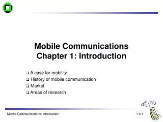
General Introduction to CDMA Mobile Communications. CDMA Business Department Shenzhen ZTE Corporation, China. Contents. Overview of Mobile Communications Technical Features of CDMA Dynamics of 3 G ( the 3 rd Generation Communications System).

General Introduction to CDMA Mobile Communications
E N D
Presentation Transcript
General Introduction to CDMA Mobile Communications CDMA Business Department Shenzhen ZTE Corporation, China
Contents • Overview of Mobile Communications • Technical Features of CDMA • Dynamics of 3 G ( the 3rd Generation Communications System)
Basic Concepts of Cellular Mobile Communication • Cell/sector • Frequency Reuse • Handoff • Cell-splitting
Characteristics of Mobile Communication • Mobility: • flexible and convenient,global personal communication • Poor environment and conditions : • Co-channel interference, multi-path(space and time)shadow effect and delay, power change and other noise, • MultipleMS and channels: • Interference 、near and far effect • Limit of frequency resources • Reliability is a must • registration, handoff, switching, control
Evolution of Mobile Communications System • 1946 First mobile phone system , 120 KHZ( AT&T): FM • 60’s IMTS 25-30KHZ (Bell System): FM • 1 G Analog Cellular/FDMA • AMPS (US, 800 MHZ/30KHZ/10 kbps) • TACS (British, 900 MHZ/25 KHZ/8 kbps) • 2 G digital cellular/TDMA • GSM, DAMPS, JDC • IS-95 CDMA • 3G IMT-2000 (International Mobile telecommunications) • UTRA/W-CDMA (Japan, Europe) • CDMA 2000 MC (US) • UTRA TDD (Europe) and TD-SCDMA(China) • UWC-136 (TDMA) • DECT (TDMA)
Concepts: FDMA, TDMA & CDMA FDMA TDMA CDMA
FDMA Power Frequency Time TDMA Power Frequency Time CDMA Power Frequency Time Channel Structure For FDMA/TDMA/CDMA Channel: An individually-assigned, dedicated pathway through a transmission medium for one user information Any of the dimensions of the transmitted signal can be segmented into private assigned channels for users. Here how the three most popular technologies establish channels: • FDMA:Frequency Division Multiple Access • each user on a different frequency • a channel is a frequency • TDMA: Time Division Multiple Access • each user on a different window period in time slot • a channel is a specific time slot on a specific frequency • CDMA: Code Division Multiple Access • each user uses the same frequency all the time, but mixed with different distinguishing code patterns • a channel is a unique code pattern
Comparison between CDMA & GSM System (1) • Cell Coverage • CDMA: varies with traffic load • No load: 3 × GSM coverage • 20 channels/sector: 2 × GSM coverage • GSM: coverage not affected by traffic load • Number of BTS • CDMA=20% × GSM • 1000 km2 coverage: CDMA 45 BTS, GSM 200 BTS • Capacity: • CDMA=5 × GSM=10 × AMPS
1 1 1 1 1 1 1 1 1 1 1 1 1 1 1 1 1 1 1 1 1 1 GSM:N=4 CDMA:N=1 2 4 3 1 4 2 3 4 1 4 2 2 3 1 1 4 2 3 4 Comparison between CDMA & GSM System (2) • Voice quality: vocoder • CDMA 8K> GSM 13K, CDMA 13K approaches 64K PCM • Handoff • CDMA : soft handoff, GSM: hard handoff, more dropped calls • Network Planning and Expansion • CDMA : simple ( N=1), GSM: more complicated (N=4/7)
Contents • Overview of Mobile Communications • Technical Features of CDMA • Dynamics of 3 G ( the 3rd Generation Communications System)
Technical Features of CDMA • Spread Spectrum • Ensures high transmission and voice quality, security • Short PN, long PN and Wash codes are used for coding • Multiple Access • Code Division:Improve frequency reuse and guarantee large capacity • Soft Handoff • Seamless communication without call dropping • High communication quality • Power Control • Ensure optimum power level with least interference to other channels, reducing Near and Far Effect and thus increasing capacity • Low radiation and longer battery usage time • Diversity Receiver (Rake Receiver) • Achieve signal gain and avoid Multi-path Effect • Voice Activation • Lower transmitting power and low speed • Voice Coding
Spread Spectrum-Basis for CDMA Technology • Definition: • Spread spectrum technique ,employ a transmission bandwidth that is several orders of magnitude greater than the minimum required signal bandwidth. • Theoretic Basis: Shannon’s Law • C=Blog2(1+S/N) C: Channel Capacity B: bandwidth S/N: signal to noise ratio Conclusion: When C is a fixed value, S/N is a reciprocal ratio of B • Another techniques for Spread Spectrum: • DSSS: Direct Sequence Spread Spectrum • FHSS: Frequency Hopping Spread Spectrum
Narrowband Signal Slow Information Sent Slow Information Recovered TX RX Spread Spectrum Principles TRADITIONAL COMMUNICATIONS SYSTEM Traditional radio communication systems transmit data using the minimum bandwidth required to carry it as a narrowband signal, e.g. FDMA and TDMA systems.
Spread Spectrum Principles (Continued) SHANON Formula C = Blog2(1+S/N) Where, C is capacity of channel, b/s B is signal bandwidth, Hz S is average power for signal, W N is average power for noise, W It is the basic principle and theory for spread spectrum communications.
Wideband Signal Slow Information Sent Slow Information Recovered TX RX Fast Spreading Sequence Fast Spreading Sequence Spread Spectrum Principles (Continued SPREAD-SPECTRUM SYSTEM Direct-Sequence Spread spectrum systems mix their input data with a fast spreading sequence and transmit a wideband signal • The spreading sequence is independently regenerated at the receiver and mixed with the incoming wideband signal to recover the original data
Spread Spectrum Principles (Continued) Processing Gain For SPREAD-SPECTRUM SYSTEM Gp=10log (B/Bm) Where, Gp is processing gain, dB B is spreading signal bandwidth, Hz Bm is original signal bandwith, Hz E.g., it is 21 dB for IS-95A CDMA system. The de-spreading gives substantial gain proportional to the bandwidth of the spread-spectrum signal The gain can be used to increase system performance and range, or allow multiple coded users, or both
Input A: User Data XOR Exclusive-OR Gate 1 Input B: Spreading Code Spread Spectrum Signal Input A: Received Signal XOR Exclusive-OR Gate Input B: Spreading Code Output: User Original Data 1 Basic Spreading & DeSpreading Example User Data Spread, Sent, Recovered At Originating Site: • Input A: User’s Data @ 19,200 bits/second • Input B: Walsh Code #23 @ 1.2288 Mcps • Output: Spread spectrum signal At Destination Site: • Input A: Received spread spectrum signal • Input B: Walsh Code #23 @ 1.2288 Mcps • Output: User’s Data @ 19,200 bits/second just as originally sent via air interface
Spread Spectrum (1) Antenna Antenna Source Coding Source Decoding Channel Coding (SS) Carrier Modulation Carrier Demodulation Channel Decoding Radio Channel Transmit Receive DS-PN DS-PN Source Decoding Source Coding Channel Decoding Carrier Demodulation Carrier Modulation Channel Coding (SS) Radio Channel Receive Transmit DS-PN DS-PN B A
Spread Spectrum (2) S(f) S(f) Signal Signal f0 f f0 f Signal Frequency Before SS Signal Frequency after SS S(f) S(f) Signal Noise Noise Signal f0 f f0 f Signal Frequency Before Decoding Signal Frequency After Decoding Signal Pulse Noise Other Noise
Spread Spectrum (3)- Spreading Codes • Spreading Code Rate: 1.2288Mc/s • Multi-path separation,(delay:1--100µs) Delay<1 µs , rate>1 MHZ • Multiples of base band rate 9.6 kbps • Spreading Codes • Forward : Walsh code • Reverse: Long PN Codes (242-1)
Spread Spectrum (4) Advantages: • Avoid interference arising from jamming signal or multi-path effects • SS and demodulation, noise is suppressed and filtered • Security: difficult to detect • Privacy: Difficult to demodulate • Multiple Access: • Improve Frequency Reuse • Enlarge Capacity
ORIGINATING SITE DESTINATION Spread Data Stream Input Data Recovered Data Spreading Sequence Spreading Sequence CDMA Spreading Principle Single spreading sequence are reversible Any data bitstream can be combined with a spreading sequence The resulting signal can be de-spreading and the data stream recovered if the original spreading sequence is available and properly timed After de-spreading, the original data stream is recovered intact Note - The spread sequences actually shown are icons, not accurate or to scale
ORIGINATING SITE DESTINATION Spread-Spectrum Chip Streams X+A X+A+B X+A+B+C X+A+B X+A Input Data X Recovered Data X Spreading Sequence A Spreading Sequence B Spreading Sequence C Spreading Sequence C Spreading Sequence B Spreading Sequence A CDMA Spreading Principle (Continued) Multiple successivesequence are reversible Multiple spreading sequences can be applied in succession and then reapplied in opposite order, to recover the original data stream • the spreading sequences can have different desired properties All spreading sequences originally used must be available in proper synchronization at the recovering destination Note - The spread sequences actually shown are icons, not accurate or to scale
Code Division Multiple Access (1) • Orthogonal Walsh function • Forward link: Spreading and building of coded channels • Reverse link: orthogonal modulation of MS signal • Long PN Code ( cycle length: 242 –1) • Forward link: identification of MS • Reverse link: Spreading and user MS identification • Short PN Code (cycle length: 215-1) • Forward and Reverse link: both for orthogonal QPSK modulation, with different phase for different BS and identical phase for different MS (0 offset)
Code Division Multiple Access (2) Division of Channels • Forward Link • Pilot: continuous transmission, for synchronization and handoff, no message • Synchronization : for the mobile to capture initial timing or synchronization when initializing • Paging Channel: for the transmission of system message and paging message, registration and traffic channel assignment • Forward Traffic Channel: transmission of voice, data and related signalling • Reverse Link • Access : used for initiating communication with BS and responding to paging message ( 1 Paging channel corresponds to up to32 access ) • Reverse Traffic: for transmission of user and signalling information during call establishment.
Forward CDMA Channels Pilot Sync. Paging Paging Traffic Traffic W0 W32 W1 W7 W8 W62 W63 User traffic MSpower control Sub-channel Reverse CDMA Channels Access Access Traffic Traffic Traffic Traffic Code Division Multiple Access (3)
Unique Properties: Mutual Orthogonality 0 0 0 0 0 0 0 1 0 1 0 0 1 0 0 1 1 EXAMPLE: Correlation of Walsh Code #23 with Walsh Code #59 #23 0110100101101001100101101001011001101001011010011001011010010110 #59 0110011010011001100110010110011010011001011001100110011010011001 Sum 0000111111110000000011111111000011110000000011111111000000001111 Correlation Results: 32 “1”, 32 “0”: Orthogonal!! 0 1 1 0 CDMA Spreading Code Walsh Code WALSH CODES # ---------------------------------- 64-Chip Sequence ------------------------------------------ 0 0000000000000000000000000000000000000000000000000000000000000000 1 0101010101010101010101010101010101010101010101010101010101010101 2 0011001100110011001100110011001100110011001100110011001100110011 3 0110011001100110011001100110011001100110011001100110011001100110 4 0000111100001111000011110000111100001111000011110000111100001111 5 0101101001011010010110100101101001011010010110100101101001011010 6 0011110000111100001111000011110000111100001111000011110000111100 7 0110100101101001011010010110100101101001011010010110100101101001 8 0000000011111111000000001111111100000000111111110000000011111111 9 0101010110101010010101011010101001010101101010100101010110101010 10 0011001111001100001100111100110000110011110011000011001111001100 11 0110011010011001011001101001100101100110100110010110011010011001 12 0000111111110000000011111111000000001111111100000000111111110000 13 0101101010100101010110101010010101011010101001010101101010100101 14 0011110011000011001111001100001100111100110000110011110011000011 15 0110100110010110011010011001011001101001100101100110100110010110 16 0000000000000000111111111111111100000000000000001111111111111111 17 0101010101010101101010101010101001010101010101011010101010101010 18 0011001100110011110011001100110000110011001100111100110011001100 19 0110011001100110100110011001100101100110011001101001100110011001 20 0000111100001111111100001111000000001111000011111111000011110000 21 0101101001011010101001011010010101011010010110101010010110100101 22 0011110000111100110000111100001100111100001111001100001111000011 23 0110100101101001100101101001011001101001011010011001011010010110 24 0000000011111111111111110000000000000000111111111111111100000000 25 0101010110101010101010100101010101010101101010101010101001010101 26 0011001111001100110011000011001100110011110011001100110000110011 27 0110011010011001100110010110011001100110100110011001100101100110 28 0000111111110000111100000000111100001111111100001111000000001111 29 0101101010100101101001010101101001011010101001011010010101011010 30 0011110011000011110000110011110000111100110000111100001100111100 31 0110100110010110100101100110100101101001100101101001011001101001 32 0000000000000000000000000000000011111111111111111111111111111111 33 0101010101010101010101010101010110101010101010101010101010101010 34 0011001100110011001100110011001111001100110011001100110011001100 35 0110011001100110011001100110011010011001100110011001100110011001 36 0000111100001111000011110000111111110000111100001111000011110000 37 0101101001011010010110100101101010100101101001011010010110100101 38 0011110000111100001111000011110011000011110000111100001111000011 39 0110100101101001011010010110100110010110100101101001011010010110 40 0000000011111111000000001111111111111111000000001111111100000000 41 0101010110101010010101011010101010101010010101011010101001010101 42 0011001111001100001100111100110011001100001100111100110000110011 43 0110011010011001011001101001100110011001011001101001100101100110 44 0000111111110000000011111111000011110000000011111111000000001111 45 0101101010100101010110101010010110100101010110101010010101011010 46 0011110011000011001111001100001111000011001111001100001100111100 47 0110100110010110011010011001011010010110011010011001011001101001 48 0000000000000000111111111111111111111111111111110000000000000000 49 0101010101010101101010101010101010101010101010100101010101010101 50 0011001100110011110011001100110011001100110011000011001100110011 51 0110011001100110100110011001100110011001100110010110011001100110 52 0000111100001111111100001111000011110000111100000000111100001111 53 0101101001011010101001011010010110100101101001010101101001011010 54 0011110000111100110000111100001111000011110000110011110000111100 55 0110100101101001100101101001011010010110100101100110100101101001 56 0000000011111111111111110000000011111111000000000000000011111111 57 0101010110101010101010100101010110101010010101010101010110101010 58 0011001111001100110011000011001111001100001100110011001111001100 59 0110011010011001100110010110011010011001011001100110011010011001 60 0000111111110000111100000000111111110000000011110000111111110000 61 0101101010100101101001010101101010100101010110100101101010100101 62 0011110011000011110000110011110011000011001111000011110011000011 63 0110100110010110100101100110100110010110011010010110100110010110 64Sequences, each 64 chips long Each Walsh Code is precisely Orthogonal with respect to all other Walsh Codes H H n n = H 2n ___ H H n n
( G E N E R A T E D I N T A P - S U M M E D S H I F T R E G I S T E R ) 1 1 0 0 0 1 1 0 0 0 P E R M U T E D E S N CDMA Spreading Code(Continued) Long Code Long CodeState (@ 1.2288 MCPS) + Public Long CodeMask (STATIC) = S U M User Long Code (@1.2288 MCPS) one chip at a time Modulo-2 Addition 0 Every User’s Long Code is 242 chips long Generated at 1.2288 Mcps, it requires 41.4 days to complete Each phone has a world-unique User Long Code generated using its 32-bit ESN, an Operator-Definable 10-bit User Mask, and the current long code state expressed as a 42-bit binary number Users Long Codes are not exactly orthogonal but are sufficiently different to permit reliable decoding on the reverse link
I Q Unique Properties: Short PN Sequence vs. Itself @ 0 Offset I Q I Q Total Correlation: All bits = 0 Short PN Sequence vs. Itself @ Any Offset I Q I Q Orthogonal: 16,384 “1 “ + 16,384 “0” CDMA Spreading Code(Continued) Short Code 32,768 chips long 26.666 ms. (75 repetitions in 2 sec.) The PN Sequence is 32,768(215) chips long • a two-dimensional binary sector with distinct I and Q component sequences, each 32,768 chips long The PN Sequence (and any sequence) correlates with itself perfectly if compared at a timing offset of 0 chips The Short PN Sequence is special: Orthogonal compared with itself using any possible timing offset other than 0
Cell Type of Sequence HowMany Length Special Properties Forward Link Function Reverse Link Function Walsh Code 64 64 chips 1/19,200 sec. Mutually Orthogonal User identity within logic channel Modulation Short Code 1 32,768 chips 26-2/3 mS 75x in 2 sec. Orthogonal with itself at any time shift value Distinguish Cells & Sectors Quadrature Spreading (Zero offset) Long Code 1 242 chips ~40 days near-orthogonal if shifted Data Scrambling to distinguish users Distinguish users, allow recovery CDMA Spreading Code(Continued) Summary of Characteristics & Functions • Each CDMA spreading sequence is used for a specific purpose on the forward link and a different purpose on the reverse link • The sequences are used to form code channels for users in both directions Forward Link
Forward CDMA channel modulation process Data scrambling Power contrl bit Convolutional Encoder and Repetition interleaver r=1/2,K=9 User data from BS in 9600bps 4800bps 2400bps 1200bps MUX 19.2kbps Walsh code Q I 4 Base band Filter Base band Filter Long code for user Long code generator Decimator Decimator 800Hz 1.2288Mcps I-channel Pilot PN Sequence Q- channel Pilot PN Sequence
Reverse IS-95 channel modulation for a single user I、Q :Zero-offset Pilot Sequence Long Code Mask for user PN chip 1.2288Mcps Long Code Generator 64-ary Ortho- gonal Modulator Data Burst Rand- omizer Conver lutional Encoder and Repetition r=1/3 K=9 Block Inter- leaver Information Bit 9600bps 4800bps 2400bps 1200bps Code Symbol 28.8kbps Code Symbol Walsh chip 307.2 kcps PN chip I-channel Base- band Filter I(t) Q-channel Baseband Filter D Q(t) 1/2 PN chip Delay=406.9ns
What is mask ? Access channel long code mask: 41 33 32 28 27 25 24 9 8 0 110001111 ACN PCN BASE_ID PILOT_PN ACN:number of access channel;PCN:number of paging ch BASE_ID, PILOT_PN. Public long code mask: 41 32 31 0 1100011000 Permuted ESN
Different approaches to bandwidth problem FDMA TDMA CDMA
BTS Pilot Walsh 0 Paging Walsh 1 PN OFFSET 116 Walsh 6 BTS Walsh 11 PN 372 WALSH 19 Walsh 19 x ANALOG SUM Walsh 20 PN OFFSET 372 Sync Walsh 32 Walsh 37 Walsh 41 x Walsh 42 PN OFFSET 226 BTS Walsh 55 x Walsh 55 PN OFFSET 511 Walsh 60 BTS Coding Process on CDMA Forward Channels Each user is assigned one of the 64 Walsh Codes and their traffic is mixed with the Walsh code to establish a dedicated code channel • Each Users Long code is applied incidentally for data scrambling All user code signals are then analog-summed to produce one composite waveform The composite waveform is the combined with the PN sequence using a specific offset to uniquely identify this cell sector
Pilot Walsh 0 Paging Walsh 1 Walsh 6 Walsh 11 Walsh 19 Walsh 20 Sync Walsh 32 Walsh 37 Walsh 41 Walsh 42 Walsh 55 Walsh 55 Walsh 60 Functions of the CDMA Forward channels PILOT: WALSH CODE 0 • The Pilot is a structural beacon which does not contain a character stream. It is a timing source used in system acquisition and as a measurement device during handoffs SYNC: WALSH CODE 32 • This carries a data stream of system identification and parameter information used by mobiles during system acquisition PAGING: WALSH CODES 1 up to 7 • There can be from one to seven paging channels as determined by capacity needs. They carry pages, system parameters information, and call setup orders TRAFFIC: any remaining WALSH codes • The traffic channels are assigned to individual users to carry call traffic. All remaining Walsh codes are available, subject to overall capacity limited by noise
Power Integration Analog Summing Output Bits#1 #2 Input Bits#1 #2 Spreading De-Spreading A + 0 User A X User A Walsh 0 Walsh 0 B + 1 User B X User B Walsh 1 C + 2 Walsh 1 User C User C X Walsh 2 D + 3 In CDMA, this is the air interface User D Walsh 2 Walsh 3 User D X Walsh 3 Analog Summing for Multiple Access This simplified demonstration shows analog summing using only four abbreviated Walsh codes, each 4 bits long. Four users are talking. Each user signal is XORed with their assigned Walsh code, and the results are analog-summed and sent over a single medium, much like in CDMA. At the other end, the Walsh codes are applied to recover each user data.
User Long Code BSC MSC BTS Coding Process on CDMA Reverse Channels Each mobile is uniquely identified by an offset of the User Long Code, which it generates internally All mobiles transmit simultaneously on the same 1.25-MHz wide frequency band Any nearby BTS can dedicate a channel element to the mobile and successfully extract its signal Mobiles also use the other CDMA spreading sequences, but not for channel-identifying purposes Short PN Sequence is used to achieve phase modulation Walsh Codes are used as symbols to give ultra-reliable communications recovery at the BTS
BTS 911 REG Functions of the CDMA Reverse channels ACCESS: It is used by mobiles not yet in a call to transmit registration requests, call setup requests, page responses, order responses, and other signalling information • an access channel is defined by a special public long code mask • Access channels are paired with Paging Channels. There can be up to 32 access channels per paging channel TRAFFIC:It is used by individual users during their actual calls to transmit traffic to the BTS • a traffic channel is defined by a specific User Long Code • there are as many reverse Traffic Channels as there are CDMA phones in the world
Technical Advantages of CDMA Technology • For the Telecom Service Provider • High Efficiency of Frequency Utilization • Large Capacity Network • Simple Frequency Planning • Compatible with Analog Mobile Network • Smooth migration to 3G • For the Subscriber • Crystal-clear Voice Quality • Good Anti-jamming • Inter system soft handoff reduces call dropping • Low radiation and Long Standby time (long battery duration) • Reliable Security
Development of CDMA Technology • CDMA One : core technology IS95 : • IS 95A: only 1 spreading code for 1 traffic channel, 14.4 Kbps • 1980, First field test by Qualcomm • 1990, first version of CDMA UM interface standard by Qualcomm • 1995, N-CDMA standard IS-95A by TIA • IS 95B : max. 8 codes for 1 traffic channel (one user for high-speed packet data service • enhanced Air interface, hardware compatible with IS-95A • 64 kbps dual way data service , • CDMA 2000 :144K/384K/2M bps • CDMA 2000-1X: 144 kbps • CDMA 2000-3X: 2 Mbps (CDMA 2000-1X-EV)
Contents • Overview of Mobile Communications • Technical Features of CDMA • Dynamics of 3 G ( the 3rd Generation Communications System)
Dynamics of 3G • Background • Higher demand of QoS • Seamless internal roaming, wideband, flexible • Large capacity, frequency resource usage • IMT-2000 • Naming • commercial use expected in 2002 • First phase frequency band around 2 G HZ. • Requirements • QoS: voice/coverage, transmission/delay(BER<10 -3 for voice/video, BER<10 –6 for data; delay is variable with multi-media data services) • New services and capabilities: wideband service(mobile laptop, medical applications, real-time map), flexible band allocation(low rate paging message—high rate video transmission, low delay requirement for voice while absolute integrity for document) • Development and evolution: step by step evolution, investment protection • Flexibility: MS (multi-mode/frequency support international roaming), self-adaptive control (adjustment of radio channel parameters for different environment) • Mobility management: Personal communication, seamless roaming among different networks.
Other CN of IMT-2000 family UIM MT RAN CN Dynamics of 3G UIM: user identity module MT: mobile terminal RAN: radio access network CN: core network
Dynamics of 3G • RTT: Radio Transmission Technology • Proposed standards: 10 (FDD: 8 , TDD 5) • 1 – 5 : similar to WCDMA, harmonization forms 3GPP WCDMA • 7 – 8 similar to CDMA 2000, harmonization forms 3GPP2 CDMA 2000 • 9 : UWC – 136, based on IS – 136 TDMA (D-AMPS)
Dynamics of 3G Wireless Access Network • Various standards: • W-CDMA FDD, W-CDMA TDD(TD-SCDMA), CDMA-2000 Multi-carrier, UWC-136 TDMA • Widely accepted standards: • CDMA 2000 • W-CDMA • UWC-136 Core Network • ANSI TIA/EIA-41 MAP • GSM MAP
Dynamics of 3 G • Wireless Access Standards Development from 2 G to 3 G • GSM GSM-----GRPS and EDGE (up to 384 kbps)---W-CDMA (5 MHZ) • CDMA IS 95A/B(14.4-64 kbps) cdma2000-1X (144 kbps) cdma2000-3X cdma2000-1X-EV • TDMA (TIA-EIA-136) IS136 IS-136+(TIA/EIA 136-A/B) TDMA/EDGE/GRPS(384kbps) IS137 2.5 G 3 G
Dynamics of 3 G • Consolidation of ITU IMT-2000:Very complicated task • Technical difference: • SS, code chip rate, Sync. Mode, Pilot, core network(GSM-MAP and IS-41) • Conflict of interest of various parties involved: • current market status of mobile communications, IPR, interest of service provider and manufacturers • 3GPP(1998-12) • Initiated by ETSI and joined by ARIB,TCC,TI,TTA • CN: GSM-MAP, RAN: UTRA • 3GPP2(1999-1) • Initiated by TIA/ANSI and joined by ARIB, TTC, TTA • CN: ANSI/IS-41, RAN: cdma2000