Modifications Required on Model Before Meshing & Solving
This guide outlines the required modifications on the model before meshing and solving for electromagnetic simulations. It covers slicing different areas, defining boundary conditions, and optimizing the mesh for accurate results.

Modifications Required on Model Before Meshing & Solving
E N D
Presentation Transcript
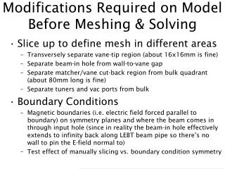
Modifications Required on Model Before Meshing & Solving • Slice up to define mesh in different areas • Transversely separate vane-tip region (about 16x16mm is fine) • Separate beam-in hole from wall-to-vane gap • Separate matcher/vane cut-back region from bulk quadrant (about 80mm long is fine) • Separate tuners and vac ports from bulk • Boundary Conditions • Magnetic boundaries (i.e. electric field forced parallel to boundary) on symmetry planes and where the beam comes in through input hole (since in reality the beam-in hole effectively extends to infinity back along LEBT beam pipe so there’s no wall to pin the E-field normal to) • Test effect of manually slicing vs. boundary condition symmetry
Sliced Geometry For Meshing Vane Cut-back Region Slice Beam In Hole Vane-tips Region Tuner Slice Vacuum Port Slice Tuner Slice Matcher Slice Bulk Quadrant Slice Bulk Quadrant Slice Bulk Quadrant Slice Each of these slices can now be individually meshed as appropriate
CST Default Mesh • Very poor mesh because: • Unnecessarily high resolution along bulk 0.5m caused by “Lower Mesh Limit” = 10 (above) • Poor longitudinal resolution of radial matcher (above) • Relatively poorly resolved quadrant, tuner & vac port (left) • Terrible transverse mesh at vane tips – only four cells! (left) • “Mesh Line Ratio” = 10 removes some necessary cells. • Resulting frequency of model = 330.027 MHz
Good Mesh To Start With • Adequate mesh because: • “Lower Mesh Limit” set to 2 removes unnecessary longitudinal resolution of bulk quadrant slices (above) • “Mesh Line Ratio” set to 100 allows high res. matcher mesh • Adequate resolution of tuner and vacuum features (above) • Vane cutback better resolved longitudinally (above) • High longitudinal resolution of matcher region (above) • More mesh cells to define quadrant, tuner & vac port (left) • 0.5mm mesh at vane tips will better resolve quadrupole field. High field regions need good resolution as they strongly affect resonant frequency! (left) • Resulting frequency of model = 324.536 MHz
Figure of merit = [1 / (V*B*L*2)] where: V = vanetips transverse mesh cell size B = bulk quadrant transverse mesh size L = smallest longitudinal mesh step in matcher region 2 = used to normalise to the best mesh able to solve
Summary – 1 • As always, mesh quality greatly affects result • CST results seem to converge to 324.2MHz but with a spread of up to 1 MHz! • Admittedly this frequency is still a bit high, but: • ANSYS 2nd order mesh consistently gives 323.2MHz for same model, so CST and ANSYS give an average result of (323.7 ± 0.5)MHz, as I presented before • This model has tuners set flush, so we do have the potential to tune down by 0.6 MHz if needed • Note that regardless of mesh, field flatness is always better than 1%
Summary – 2 • Considering CST is so inconsistent with its result (depending on who does it, whether you use symmetry or not, mesh quality and even time of day!) but ANSYS is rock-steady, I’d be more inclined to believe ANSYS’s 323.2 MHz (which is also consistent with Superfish) • However CST is right and the real thing does have a frequency closer to 324.2 MHz then it’s a problem and we shouldn’t rely on tuners • Increasing the bulk quadrant radius by 0.1mm reduces the frequency by about 0.8 MHz whereas the tuners’ effectiveness is about 0.15 MHz per mm • ∴ If we increase the quadrant radius to ensure the frequency is definitely below 324 MHz, then we’d have to constantly run with all the tuners in by at least 6mm – potentially much more depending on whether you believe ANSYS or CST! – thus reducing the Q • There may be an alternative…
If Frequency is ≲0.5MHz High • Use slug tuners for local tuning & flattening • Cut a small groove along length of RFQ for a small fixed reduction in frequency Plain 44.1mm radius RFQ quadrant Frequency = 323.36 MHz 5mm wide, 1mm deep groove cut into wall Frequency = 323.21 MHz 10mm wide, 2mm deep groove cut into wall Frequency = 322.90 MHz