Download

1 / 37
370 likes | 386 Vues
This article discusses the effects of leakage flows on turbine performance and explores methods to minimize leakage losses through the use of labyrinth seals and cavity designs. It also examines the influence of leakage on cascade pressure profiles and velocity triangles.

E N D
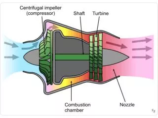
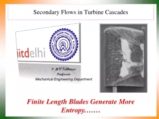
Leakage Flows in Turbine Cascades P M V Subbarao Professor Mechanical Engineering Department In a Large Group, a Fraction of Parcels Will Try to Look for Short Cuts ….
Losses by stage and section for a 700 MW turbine.Source: Toshiba
The Leakage : Temptation offered by Gaps Cascade Streamlines in the Gap Near Gap Cascade Streamlines Tempted by Gap
Fraction of Leakage Cummulative Leakage Fraction Fraction of Chord Length
Gaps in Turbines • In any kind of turbomachinery a certain gap is inevitably required between the rotating and stationary components. • The minimization of the gap is more than desirable but mechanical considerations and mainly thermal expansion of the materials set certain limits. • The presence of the tip gap over the blade usually eliminates the stagnation at the endwall. • The stangation zone typically occurs in the corner between the endwall and blade leading edge in the no-tip-gap configuration. • Therefore, a horse-shoe vortex does not feature at the tip endwall unless the tip gap is very small.
Classification of Tip Clearance Flow • The flow at the tip endwall approaching the tip region above the leading edge of the blade is divided into two streams. • These two streams are aiming towards low pressure regions at the suction surfaces of the neighbouring blades. • – a main stream of the tip leakage flow going through the tip gap over the blade and • – a stream of cross-flow going across the blade-to-blade passage.
Secondary Cross flow due to Tip Clearance The tip leakage flow leaving the tip gap separates from the endwall under conditions of adverse pressure gradient and forms a tip leakage vortex.
The cross-flow blocked by the development of the tip leakage vortex also separates from the endwall and rolls up into a passage vortex. • The stream dividing line between the tip leakage and cross-flow lies at the pressure side of the blade tip. • The tip leakage and passage vortices are characterised by the opposite sense of rotation. • Usually, a dominant structure is the tip leakage vortex. • The relations between the circulation and size of the two structures depend on many factors such as • the tip gap size and • flow turning angle.
Labyrinth Seals • The labyrinth design provides a high resistance path against steam leakage while allowing sufficient clearance between the rotor and the stationary components • Labyrinth seals reduce the amount of leakage flow that by-pass the main flow path through the rotor and increasing efficiency thus avoiding rotor rubs during operation.. • Numerous labyrinth geometries are used by the turbine designers depending on the application. • All of them consist of an inlet and exit cavity and a number of closed cavities in between. • The size of the cavities needs to be relatively large compared to the blade height to allow for the axial displacement of the rotor due to thermal growth or axial thrust variations.
Geometric Classification of LABYRINTH SEALS • Straight-through • Stepped • Staggered • Radial
Gap Flow with LABYRINTH SEALS Flow in a straight-through labyrinth seal
Effect of leakage flow on incidence angle • Leakage Losses account for a substantial part of the total Group-1 losses in shrouded turbines. • The leakage flow that is driven by the pressure difference across the rotor through the labyrinth, gets circulated inside the rotor inlet cavity by the toroidal vortex. • A part of this flow re-enters the main flow causing extensive mixing in the interaction zone. • Prior mixing of the cavity and main flows changes the incidence angle at the tip section of the blade. • The difference in flow angle between the re-injected cavity flow and the main flow is what facilitates the off-design incidence on the downstream blade row.
Challenging Efforts to Contain the Leakage Losses with Seals
The Cavities in Seals • Cavity design plays a key role in the cavity vortex formation and positioning. • The lower side of the cavity vortex should be close to the interaction zone. • A Cavity design should push the vortex to be even lower, but not extending beyond the cavity limit.
Profile design considerations at the endwalls • Design changes at the endwalls are made to counteract the growth of secondary loss. • Secondary flows although undesirable, dominate the flow field in turbines consisting a major source of loss in axial turbines • This aspect is considered to be an important additional degree of freedom that can be exploited to enhance overall design quality. • Three aerodynamic aspects were found to be of great significance in controlling secondary loss generation: • (a) higher degree of aft loading, • (b) lower maximum circumferential pressure gradient, • (c) lower diffusion on the suction side (thinner boundary layer).
Losses by stage and section for a 700 MW turbine.Source: Toshiba