Download

1 / 24
240 likes | 333 Vues
Develop a Low Noise Amplifier meeting specific gain, noise, power, and stability targets for astronomical observations at Lords Bridge. The LNA operates in the 70-450MHz range, consuming less than 100mW. It is unconditionally stable with high common-mode signal rejection. Biasing is achieved through the coax cable. The architecture includes differential source, single-ended load, and TNC connectors. Designed for Vivaldi antennas with embedded patterns and mutual coupling considerations. The LNA supports beamforming and bandpass filtering. A versatile solution for narrow and wide-band applications in radio astronomy.

E N D
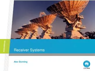
AAVS receiver Federico Perini AAVP 2011 12-16 December, 2011 - ASTRON, Dwingeloo
AAVS0 Embeddedelement Mutualcoupling
AAVS0 test sites Lord’s Bridge, Cambridge
AAVS0 test sites Medicina
AAVS0 RFI RBW=10KHz VBW=10KHz SPAN=50-500MHz Data corrected for antenna gain and coax loss
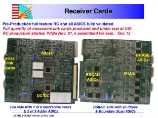
LNA for Vivaldi TNC connectors, 50Ohm I&O Vmin=3V, I=60mA (180mW) Bias through output coax cable or feed through
LNA for Logperiodic Based on AVAGO MGA-16516 Low Noise, High Linearity Match Pair Low Noise Amplifier • Frequency range 70 to 450MHz • Gain > 20dB (40dB) • Gain flatness, as flat as possible consistent with meeting other spec. parameters • Noise temperature < 30K at 450MHz • P1dB, high enough to allow astronomical observations to be made at Lords Bridge • Power consumption < 100mW (Vmin=4.5V, I=131mA) • Unconditionally stable at both input and output ports • Differential source (antenna), single-ended (50Ohm) load • High Level of Common Mode Signal Rejection • Biasing through the coax cable
AAVS0: mutual coupling • VNA Shelter
AAVS0: mutual coupling RX TX • VNA TX RX Shelter
AAVS0, 1 ,#? Embeddedelement Mutualcoupling Beamforming Bandpass Tsys …. AAVS0+ ?
SKADS/prepSKA BEST RX 3C196 radiomap obtained with the Medicina BEST-2 SKADS demonstrator array and the CASPER data processing
AAVS0+ receiver: Narrow Band ROACH ADC 65MS/s 12bit NB 1 NB NB 2 NB NB NB 3 • I/Q balancing • 1024ch spectrometer • Digital Beamformer • Digital Correlator NB NB 16
NB receiver: block diagram BOX under/close the antenna Coax from LNA FM STOP TX A A BIAS T Filter bank COUPL NG 0-180° Power to LNA NG Control & Power Supplies LO ADC 65MS/s 12bit + ROACH A Filter Filter A FILT DIG ATT RX A 0 90° Control &Power Supplies
NB receiver: LO distributor AD5387 IQ mixer LO level: Typ=0dBm (-6dBm to 6dBm) LO frequency at the input to the device have to be twice that of the desired LO frequency at the mixer core. RF from 70 to 450MHz LO from 140 to 900MHz
WB RX ROACH WB 1GS/s 8bit WB: test bandpass and stability characteristics of the RF-chain. A 1024ch spectrometer is being developed which will split the 500MHz into 500kHz channels. WB 1GS/s 8bit WB 1GS/s 8bit WB 1GS/s 8bit
WB receiver: block diagram BOX under/close the antenna Coax from LNA FM STOP TX A A COUPL BIAS T Filter Bank NG 0-180° Power to LNA NG Control & Power Supplies ADC 1GS/s 8bit + ROACH A FILT DIG ATT Pre-White RX A Control &Power Supplies
Conclusions • AAVS0: RoF links (already available) are sufficient • AAVS0+: narrow and wide band receivers are under development • OL distributor, mechanical housing and RX control by reusing BEST stuff • Back End & Firmware already available too • AAVS1: evolution of the WB AAVS0+