EDFA Simulink Model for Analyzing Gain Spectrum and ASE by Stephen Pinter
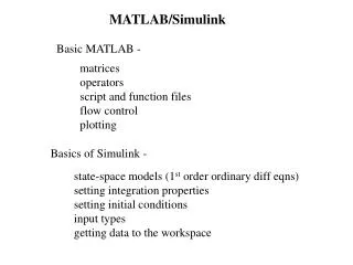
EDFA Simulink Model for Analyzing Gain Spectrum and ASE by Stephen Pinter. Presentation Overview. Project objectives Gain characteristics of EDFA wavelength dependant gain Gain flattening non-uniform gain over the spectrum implications. Project Objectives.

EDFA Simulink Model for Analyzing Gain Spectrum and ASE by Stephen Pinter
E N D
Presentation Transcript
EDFA Simulink Model for Analyzing Gain Spectrum and ASEby Stephen Pinter
Presentation Overview • Project objectives • Gain characteristics of EDFA • wavelength dependant gain • Gain flattening • non-uniform gain over the spectrum • implications
Project Objectives • Determine the optimum length for simulations • ASE not considered – optimum length is shorter when ASE taken into account • Expand the current EDFA Simulink model to show the gain over the entire 1550nm window • important to know gain in range 1530nm – 1560nm • Consider gain flattening, and • Integrate forward ASE into the EDFA model • Why Simulink?
Why use Simulink when an EDFA can be simulated using simulation tools such as OASIX or PTDS? • OASIX or PTDS • static model • input pump power is a static input internal to the EDFA module • Simulink • dynamic model • input pump power as well as other EDFA parameters can be easily modified
EDFA Gain characteristics • Significant equations governing EDFA dynamics • Output pump and signal power: • Quantities B and C characterize the physical EDFA and are given by: • To handle multiple signal wavelengths, Bs and Cs as well as the input signal must be multidimensional • Why?
and are wavelength dependant as shown in the figure • and are the absorption and emission coefficients, respectively • so, the quantities B and C are wavelength dependant • this relationship is how the wavelength dependency of the gain arises • EDFA gain ratio between the absorption and emission at a particular wavelength is critical in determining the gain
Note on Aspects of Simulation • when performing simulations on the EDFA model it is important to simulate all the wavelengths simultaneously instead of one at a time • EDFAs work in the nonlinear regime, so properties like linear superposition don’t hold true • when there are several channels in an EDFA there is an effect called gain stealing • the energy that each of the channels takes from the pump depends on the details of the emission and absorption spectra • before simulating the gain, the optimum length was determined
Optimum Length • gain varies significantly over wavelength • two distinct peaks • 12m and 30m • first peak • 1520-1536nm • choose Lopt = 12m
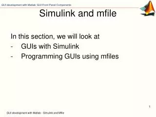
Simulink Models • implementation of the ordinary nonlinear differential equation used for studying EDFA gain dynamics • rate equation • input/output
EDFA Gain • significant gain variation is visible • about 11dB gain difference in the range 1530nm-1560nm • How do we flatten the gain?
Gain Flattening • using the equations shown earlier, I derived an equation relating the pump gain (GP) to the signal gain (GS) • the resultant equation is: • BP and CP are fixed, and BS and CS vary with wavelength • now GS can be fixed and GP for gain flatness can be obtained
for a GS of 30dB, GP should follow the curve shown in the figure • theoretical view of what the pump should be • practically, in order to get a different power at each wavelength might be difficult • something to be further analyzed