Download
1 / 154
1.54k likes | 1.67k Vues
This article explores the evolution and significance of VHDL (Very High-Speed Integrated Circuit Hardware Description Language), initiated as a U.S. Department of Defense project in the early '80s. VHDL is crucial for documenting and specifying ASICs, gaining IEEE standard status in 1987, with updates in 1992. Despite competition from Verilog, its use in circuit simulation and synthesis has flourished in industry and academia. We discuss its structure, including entity/architecture pairs, behaviors, and the impact of concurrent and sequential design. VHDL’s relevance today is showcased through examples and comparisons to software programming.

E N D
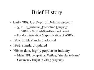
Brief History • Early ‘80s, US Dept. of Defense project • VHSIC Hardware Description Language • VHSIC = Very High Speed Integrated Circuit • For documentation & specification of ASICs • 1987, IEEE standard adopted • 1992, standard updated • ‘90s to date, highly popular in industry • Main HDL competitor: Verilog, “simpler to learn” • Commonly taught in CEng programs
Uses Evolved • Documentation & specification • Circuit simulation • Circuit synthesis
Why a “language”? • VHDL largely overlooked while schematic capture reigned • Moore’s Law put schematic capture out of business • Text-based modeling attractive → suitable input for CAD tools • Modeling, simulation, synthesis
Is it “like C”? • Yes • There are statements, block structure, variables, constants, operators, even “;” • No • SW programmers follow sequential “Von Neumann” computation model; but… • HDL statements translate into logic gates, not instructions • HW is always there, always “on”, operating concurrently → surprises SW people (example later)
Three ways to describe circuit • Structural • Instantiate specific library components and “wire” them together • Dataflow (RTL) • Instantiate register components from library • Code combo logic with high-level operations; let VHDL compiler synthesize logic gates • Behavioural • Code algorithm steps; let VHDL compiler infer components, datapath, and controller
Basic Ingredients • Structure • Entity/architecture • Behaviour • Process • Timing • Data • Signal • Variable • Logic values
x Basic Logic Gate F y architecture behav1 of AND_ent is begin process(x, y) begin -- compare to truth table if ((x='1') and (y='1')) then F <= '1'; else F <= '0'; end if; end process; end behav1; What did we observe? library ieee; use ieee.std_logic_1164.all; entity AND_ent is port(x: in std_logic; y: in std_logic; F: out std_logic ); end AND_ent; architecture behav2 of AND_ent is begin F <= x and y; end behav2; Comment Operation defined on std_logic Signal assignment (a “wire”)
Library: Abstract Data Types IEEE std_logic_1164 values U Uninitialized X Unknown 0 Zero 1 One Z High Impedance (tristate not driving output) W Weak Unknown L Weak Zero (low) H Weak One (high) - Don’t Care Why all these??
Entity/Architecture Pair • Entity → circuit’s external interface • Ports function parameters • Strongly typed: std_logic • Mode: in, out, inout (tristate), buffer (“out” that’s readable inside architecture) • Architecture → internal implementation • Multiple implementations allowed • Code block: thingbegin…endthing ;
Process • Wrapper for “sequential” statements • ( sensitivity list ) • Tells simulator to re-simulate the process when any member of list changes value • Sequential-type statements can only appear inside a process: <= If-Then-Elsif-Else Case-When • Concurrent-type statements can appear anywhere • Processes together become concurrent blocks of logic
Result of Description • Like OO class definition, entity has to be instantiated in another architecture • One behaviour chosen upon instantiation • Libraries full of entity definitions • If simulation is goal: • Both behaviours are identical • If synthesis is goal (actual AND gate): • Should anticipate what circuit compiler will create • Different from SW where normally trust compiler
Combinational Logic Design input1 input2 output Component Library “work” entity OR_GATE is port(X: in std_logic; Y: in std_logic; F2: out std_logic ); end OR_GATE; entity AND_GATE is port(A: in std_logic; B: in std_logic; F1: out std_logic ); end AND_GATE; input3 use work.all; entity comb_ckt is port(input1: in std_logic; input2: in std_logic; input3: in std_logic; output: out std_logic ); end comb_ckt; architecture follows →
A input1 F1 input2 wire B X F2 output input3 Y Combo Logic architecture struct of comb_ckt is component AND_GATE is port(A:in std_logic; B: in std_logic; F1:out std_logic ); end component; component OR_GATE is port(X: in std_logic; Y: in std_logic; F2: out std_logic ); end component; signal wire: std_logic;-- signal just like wire begin -- use sign "=>" to clarify the pin mapping Gate1: AND_GATE port map (A=>input1, B=>input2, F1=>wire); Gate2: OR_GATE port map (X=>wire, Y=>input3, F2=>output); end struct; Label for statement
a X b Y s c Example of Programmer’s “Surprise” entity … port( a, b, c: in bit; X, Y: out bit ); … signal s: bit:=‘0’; Y <= s and a; X <= a or c; s <= b or c; • What does Y output for (1,0,1) input? • As (bad) software, clearly 0 • As hardware, describes logic circuit structure • “b or c” isn’t “done after” Y<= assignment • result → 1
a state_reg reset x clock comb_logic Sequential Design entity seq_design is port(a:in std_logic; clock:in std_logic; reset:in std_logic; x:out std_logic ); end seq_design; architecture FSM of seq_design is -- define the states of FSM model type state_type is (S0, S1, S2, S3); signal next_state, current_state: state_type; begin -- concurrent process#1: -- advance state on clock going high state_reg: process(clock, reset) begin if (reset='1') then current_state <= S0; elsif (clock'event and clock='1') then current_state <= next_state; end if; end process; more → Enumerated data type Becomes state register
a state_reg reset x clock comb_logic Sequential Design -- concurrent process#2: -- compute output and next state comb_logic: process(current_state, a) begin -- use case statement to show the -- state transition case current_state is when S0 => x <= '0'; if a='0' then next_state <= S0; elsif a ='1' then next_state <= S1; end if; when S1 => x <= '0'; … when S2 => x <= '0'; … when S3 => x <= '1'; … when others => x <= '0'; next_state <= S0; end case; end process; end FSM;
Many More Features • Logic vectors & arrays type mem is array(0 to 127) of std_logic_vector(15 downto 0); • Define registers, buses, memories • Variables c := a xor b; • Temporary value, not intended to generate hardware • Timing statements wait for 10 ns; • Used for simulation • “Test bench” code connected to system-under-test can check if timing constraints met/violated
Still More Features • Libraries library ieee; • Default library = “work” • Built-in packages in “std” • Package use ieee.std_logic_1164.all; • Binds constants, types, operations into set of “abstract data types” • Configuration for Gate1: AND_ent use entity work.AND_Ent(behav2); • Selects alternative architectures when instantiating entity • Generic like C++ template parameterization
VHDL • An acronym for Very high speed integrated circuit Hardware Description Language • VHDL enables hardware modelling from the gate to system level • Allows various design methodologies • Provides technology independence • VHDL has been standardised: • VHDL 87 • VHDL 93
System Design; definition and use of its parts • A system communicates via an interface • Interface is “entity” in VHDL • Cannot have any VHDL system without an entity • Example: • entity my_entity is • ……………….. • endentity my_entity;
Architecture • The body of the system accomplishes some tasks on the data • eg data transformation • In VHDL the body is called “architecture” • Example: • architecture my_architecture of my_entity is • ………………. • begin • ……………… • end architecture my_architecture ;
Types of Architecture • Behavioural (Functional) • The system in terms of its functionality • It does not contain any information about the internal system structure • It describes the expected behaviour: What a system will do • Response of outputs to inputs • No clue as to HOW but describes WHAT a system has to do
Types of Architecture • Structural • HOW a system is composed • what components should be used • describes internal structure of system • how they should be connected • akin to a textual version of a schematic diagram
A behavioural architecture if CLK'event and CLK='1' then --CLK rising edge DOUT <= DIN;
A structural architecture A Full Adder: SUM<=A xor B xor C; CARRY<= A and B or ((A or B) and C);
A Structural Architecture • --generate construct • gen: for i in 0 to n-1 generate • --component instantiation • ins: full_adder port map (a(i), b(i), carry(i), sum(i), carry(i+1)); • end generate;
One Entity - Many Architectures • More than one way to create a design • Similarly, more than one architecture for a single entity (cf. More than one schematic to fulfil same specification) • Same interface • BUT only one entity for any architecture
Package • External source of description • Allow you to define items outside of VHDL standards • Must be declared in advance using “library” and “use” keywords, usually before entity
Few Packages • Standard (defined by the std library) • Std_logic_Textio (defined by the IEEE library) • Std_logic_1164 (defined by the IEEE library) • Plus vendor-specific
Communications • Signals: inside device or between devices • Single or multiple wire - (bus) or (vector) • Example • bit for single signals • bit_vector for multiple signals • in both cases, each signal line can be either ‘1’ or ‘0’ • For bit_vector the width of the vector must be specified using two key words: downto and to • Order important for vector • bit_vector(7 downto 0) ascending order of bits • bit_vector (0 to 7) descending order of bits
external signals • External signals connect the system to the outside: they form the system’s interface • Each external signal is specified as port inside its entity • Each external needs a unique name, a type and a direction: • input - in • output - out • bi-directional - inout
Port Syntax • port_name: port_direction port_type ; • example: port( result: inout bit_vector (0 to 7) ); • Multiple signals of different type separated by semicolons • Same type separated by commas • optional initial value, preceded by :=
Example • Example: entity ROM_MEMORY is • port ( A_ROM :in bit_vector (3 downto 0); • CS_ROM : in bit; • D_ROM : outbit_vector(7 downto 0) ); • end entity ROM_MEMORY;
Internal signals • Internal signals declared inside an architecture • The keyword signal is required to declare an internal signal • Internal signals do not require a direction • It is possible to specify an initial value for an internal signal
Generics • Method of providing constant values for different parameters. • Must be in entity, before ports • Need the keyword ‘generic’, name, type, value, optional comment • example • generic (BusWidth : integer:= 2; • MaxDelay : time:= 100 ns ) ; • Can be used anywhere a constant is needed
Generics • Can be used anywhere a constant is needed • Parameters are typically specified by generics: • The size of some objects such as arrays or buses • Timing parameters • Useful in structural and behavioral models
Standard Data Types • Enumeration types ( Boolean, bit, character) • Integer type • Real type • Physical type (time) • Standard array types ( string, bit_vector)
Enumeration types • Bit • 0,1 • not same as Boolean in VHDL • Boolean • true, false • Character • all characters in ISO 8859-1 (West European) • eg ‘0’, ‘1’, ‘X’
Integer and real types • Integer • implementation dependent • must include -2147483647 to +2147483647 • Real • implementation dependent • must include -1.0E308 to +1.0E308
Physical Types • They specify the object values and the units they are expressed in. • VHDL defines only one: time • Note primary and secondary units
Predefined arrays • Arrays are collections of elements of the same type • The number of elements is specified by a range • Predefined VHDL arrays are: • bit_vector (first element is 0) • and string (first element is 1) • single element in single quotes ‘’, multiple element double quotes ”” • one-dimensional
User-defined Types • Use the keywords type or subtype • Example: • type short isrange -128 to 127; • subtype natural isintegerrange 0 to 147483647; • ( subtype of the integer type) • type FSMstates is( idle, decode, execute ); • ( a user defined enumerated type) • type TYPE_NAME is array (0 to 31) of BIT; • ( user defined array of element of type bit)
Signal Assignment • Uses <= • Target on left • eg a <= b or c • arrow denotes flow of information • not, and , or, nand, nor, xor, xnor • not has highest precedence • all others equal and are evaluated left to right
Example 2-Input AND Entity And2 is port (x,y : in bit; z : out bit); end entity And2; Architecture ex1 of And2 is begin z <= x and y; end architecture ex1;
Logical operators • not, and , or, nand, nor, xor, xnor • They accept operands of type BIT, Boolean and bit_vector. • If the operands are of type bit_vector, they must be of the same size • a sequence of logical operators requires parentheses. • Example: • a and b or c and d; -- wrong • (a and b) or (c and d); --correct
Arithmetic Operators • Addition ‘+’, subtraction ’-’,multiplication ‘*’, division ‘/ ‘, modulus ‘mod’, remainder ‘rem’, exponentiation ‘**’ and absolute value ‘abs’ • Predefined for • integer • real ( except ‘mod’ and ‘rem’) • time Not defined for bit_vector ‘+’ and ‘- ‘ can also be used as unary operators ( sign operators)
Arithmetic Operators • Operands of same type (except exponentiation : exponent always integer) • an operand of type time can be multiplied or divided by an integer (result of type time) • order of precedence: • exponentiation ‘**’ • multiplication ‘*’, division ‘/’ • unary sign operators ‘+’ and ‘-’ • addition ‘+’ and subtraction ‘-’ • Example: 3+4*5=23, (3+4)*5=35
Relational operators • The operators equal ‘=‘, not equal ‘/=‘, less than ‘<‘, greater than ‘>’, less than or equal ‘<=‘, greater than or equal ‘=>’, compare objects of the same type • Result always BOOLEAN (true or false) • Bit_vectors operands do not need to be of the same length: both operands are left justified
Shift Operators • Applied only on the one-dimensional array • with the elements of the type BIT or BOOLEAN • srl, sll, ror, rol, sla, sra • ‘0’ shifted in for type bit, false for type Boolean • Example: z_bus <=a_bus sll 2;
Concatenation • Allows creation of a new array from several others • ‘&’ is the concatenation operator • Length of new array is sum of length of both operands • Example: signal a, b: bit_vector (3 downto 0); signal z: bit_vector (7 downto 0); z <= a & b;