Download
1 / 10
110 likes | 325 Vues
CSE 140L Lecture 4 Flip-Flops, Shifters and Counters. Professor CK Cheng CSE Dept. UC San Diego. F-F Shift register Counter (Asynchronous) Counter (Synchronous). Flip-Flops. D. DFF. Asynchronous Clear. Q. Inputs Output. CE. C. CLR CE D C Q

E N D
CSE 140L Lecture 4Flip-Flops, Shifters and Counters Professor CK Cheng CSE Dept. UC San Diego
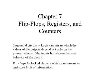
F-F • Shift register • Counter (Asynchronous) • Counter (Synchronous)
Flip-Flops D DFF Asynchronous Clear Q Inputs Output CE C CLR CE D C Q 1 X X X 0 0 0 X X No change 0 1 1 1 0 1 0 0 CLR Clock Enable CLK = 1 CLK = 0
D-FF Timing Q D CLK CLK tsetup thold t D t Q t tcq
Input Timing Constraints • Setup time: tsetup = time before the clock edge that data must be stable (i.e. not changing) • Hold time: thold = time after the clock edge that data must be stable • Aperture time: ta = time around clock edge that data must be stable (ta = tsetup + thold)
Output Timing Constraints • Propagation delay: tpcq = time after clock edge that the output Q is guaranteed to be stable (i.e., to stop changing) • Contamination delay: tccq = time after clock edge that Q might be unstable (i.e., start changing)
Setup Time Constraint • The setup time constraint: The maximum delay from register R1 through the combinational logic. • The input to register R2 must be stable at least tsetup before the clock edge. Tc ≥ tpcq + tpd + tsetup tpd ≤ Tc – (tpcq + tsetup)
Hold Time Constraint • The hold time constraint depends on the minimum delay from register R1 through the combinational logic. • The input to register R2 must be stable for at least thold after the clock edge. thold < tccq + tcd tcd > thold - tccq
2) A 3 Bit Shift Register B D C A Q Q Q D D D CLK Time Steps A B C D • 0 0 X X X • 1 0 X X • 2 0 1 0 X • 1 0 1 0 • 1 1 0 1 • 0 1 1 0 • 0 0 1 1 • 1 0 0 1 Signal A is given as input.
3) A 3 Bit Counter (Asynchronous) A B C Q Q Q 1 1 T T 1 T CLK Reset A(0) = B(0) = C(0) = 0 Time C B A • 0 0 0 0 0 • 1 1 1 7 • 2 1 1 0 6 • 1 0 1 5 • 1 0 0 4 • 0 1 1 3 • 0 1 0 2 • 0 0 1 1 CLK t A 1 0 1 0 t B 1 1 0 0 t C 1 1 1 1 t 7 6 5 4