Parallel Ports
Parallel Ports. Dr. Iyad Jafar. Outline. Why Do We Need Parallel Ports? Hardware Realization of Parallel Ports Interfacing to Parallel Ports The PIC 16F84A Parallel Ports . Why Do We Need Parallel Ports?.

Parallel Ports
E N D
Presentation Transcript
Parallel Ports Dr. Iyad Jafar
Outline • Why Do We Need Parallel Ports? • Hardware Realization of Parallel Ports • Interfacing to Parallel Ports • The PIC 16F84A Parallel Ports
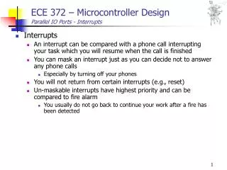
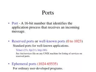
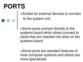
Why Do We Need Parallel Ports? • Almost any microcontroller needs to transfer digital data from/to external devices and for different purposes • Direct user interface – switches, LEDs, keypads, displays • Input measurement - from sensors, possibly through ADC • Output control information – control motors and actuators • Bulk data transfer – to other systems/subsystems • Transfer could be serial or parallel !
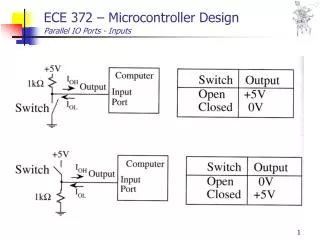
Hardware Realization of Parallel Ports Output Parallel Port
Hardware Realization of Parallel Ports Input Parallel Port
Hardware Realization of Parallel Ports Bidirectional Parallel Port
The PIC 16F84 Parallel Ports PORT B • 8-bit general-purpose bidirectional digital port • Pin RB0 is multiplexed with the external interrupt INT and has Schmitt trigger interface • Data from/to this port is stored in PORTB register (0x06) • Pins can be configured for input or output by setting or clearing corresponding bits in the TRISB register (0x86) • Pins RB4 – RB7 have a useful ‘interrupt on change’ facility
The PIC 16F84 Parallel Ports Configurable pull-up resistors using RBPU bit in the OPTION register PORT B Latches input data whenever the port is read Multiplexed input
The PIC 16F84 Parallel Ports PORT B Lathes data on port read Holds previous latched data Clearing the RBIF bit ? Compares previous and present port input values
The PIC 16F84 Parallel Ports PORT A • 5-bit general-purpose bidirectional digital port • Pin RA4 is multiplexed and can be used as the clock for the TIMER 0 module • Data from/to this port is stored in PORTA register (0x05) • Pins can be configured for input or output by setting or clearing corresponding bits in the TRISA register (0x85)
The PIC 16F84 Parallel Ports PORT A
The PIC 16F84 Parallel Ports • Example – configuring port B such that pins 0 to 2 are inputs, pins 3 to 4 outputs, and pins 5 to 7 are inputs bcf STATUS, RP0 ; select bank0 clrf PORTB ; clear port B latches bsf STATUS , RP0 ; select bank1 movlw 0xE7 movwf TRISB ; PORTB<7:5> input, ; PORTB<4:3> output ; PORTB<2:0> input
Example on Using I/O Ports • Example – on external interrupt (rising edge ON RB0), start flashing a LED connected to RB1 every 1 ms. If another interrupt occurs, stop flashing, and so on … assume 4MHz clock. • Requirements: • Configure RB0 as input and RB1 as output • Enable external interrupt (INTE) and global interrupts (GIE) • Write a 1 ms delay routine • Keep track of the current status of flashing (on/off)
Example on Using I/O Ports #include P16F84A.INC FLASH EQU 0X20 ; STORE THE STATE OF FLASHING COUNT EQU 0X21 ; COUNTER FOR DELAY LOOP ORG 0X0000 GOTO START ORG 0X0004 GOTO ISR ; ---------------------------------- MAIN PROGRAM ----------------------------------------------- START CLRF FLASH ; CLEAR FLASHING STATUS BSF STATUS,RP0 ; SELECT BANK 1 MOVLW B'00000001' ; CONFIGURE RB0 AS INPUT AND RB1 AS OUPUT MOVWF TRISB BSF OPTION_REG, INTEDG ; SELECT RISING EDGE FOR EXTERNAL INTERRUPT BSF INTCON , INTE ; ENABLE EXTERNAL INTERRUPT BSF INTCON , GIE ; ENABLE GLOBAL INTERRUPT BCF STATUS,RP0 ; SELECT BANK 0 CLRF PORTB ; CLEAR PORTB WAIT BTFSS FLASH , 0 ; IF BIT 0 OF FLASH IS CLEAR THEN NO FLASHING GOTO WAIT ; WAIT UNTIL BIT 0 IS SET MOVLW B'00000010' XORWF PORTB , 1 ; COMPLEMENT RB1 TO FLASH CALL DEL_1MS GOTO WAIT
Example on Using I/O Ports ; ---------------- DELAY ROUTINE ------------------------ DEL_1MS NOP MOVLW D'142' MOVWF COUNT LOOP NOP NOP NOP NOP DECFSZ COUNT , 1 GOTO LOOP RETURN ; DELAY = (2+1+1+1+(4+1+2)*141+(4+2+2)*4/4MHz = 1ms ; --------------- INTERRUPT SERVICE ROUTINE --------------- ISR XORWF FLASH , 1 ; COMPLEMENT THE STATUS BCF INTCON , INTF ; CLEAR THE INTF FLAG RETFIE END