Download
1 / 24
240 likes | 283 Vues
Final report outlining the EV concept, mechanical composition, hybrid vehicle design, energy management, simulations tools, and electric motor and ICE criteria for efficient powertrains in electric vehicles and its advantages over traditional systems. This report discusses the need for electric vehicles due to increasing automobiles, declining oil reserves, greenhouse emissions, and global warming regulations while addressing the use of alternate fuels, new materials, and power systems. It delves into the various types of EVs, their characteristics, energy sources, infrastructure, limitations, and major issues faced in the industry, as well as the importance of vehicle modeling and simulation tools in optimizing powertrain design to meet performance criteria.

E N D
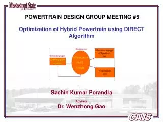
Powertrain Design Group Meeting #1Final Report of “Automotive Powertrain System”
Outline • Why Electric vehicle?? • EV concept and technologies (BEV, HEV, FCEV etc.) • Learn EV Mechanical Composition • Vehicle modeling and simulation tools • Parallel Hybrid Vehicle Design • performance criterion • road load characteristics • electric motor and ICE design • Energy Management System • Know about batteries and battery modelling • Electric vehicle simulation • HEV simulation
Why Electric Vehicles? • Increasing automobiles • Declining oil reserves • Increasing greenhouse emissions • Global warming, CARB regulations Solution: improve the existing power system efficiency, alternate fuels, new materials or alternate power systems like electric vehicles First solution may not solve the problem in long run. So, look for the other three.
Electric Vehicle concept • EV is a road vehicle based on modern electric propulsion consisting of electric machines, power electronic converters, electric energy sources and storage devices, and electronic controllers; • EV is a broad concept, including BEV, HEV, FCEV, etc; • Regenerative breaking is possible in EVs; • EV is not only just a car but a new system for our society’s clean and efficient road transportation; • EV is an intelligent system which can be integrated with modern transportation networks; • EV design involves the integration of art and engineering; • More advancements are to be done to make them affordable;
EV Mechanical compostion Three major components and interconnections propulsion system wheels auxiliary power energy source Electric Propulsion system: generates the necessary power to the wheels. Includes transmission and energy management system Energy source: consists of energy sources like fossil fuel, battery or fuel cells. Generates or accepts energy Auxiliary power system : supplies power to auxiliaries like a.c., fan, lightning system etc.
Comparison of BEV, HEV, and FCEV Types of EVs BEV HEV FCEV Propulsion • Electric motor drives • Electric motor drives • ICE • Electric motor drives Energy system • Battery • ultracapacitor • Battery • Ultracapacitor • ICE generating unit • Fuel cells Energy source and infrastructure • Electric grid charging facilities • Gasoline stations • Electric grid charging facilities (optional for plug-in hybrid) • Hydrogen • Methanol or gasoline • ethanol Characteristics • Zero emission • Independence on fossil oil • Commercially available • Low emission • Higher fuel economy • Commercially available • Zero emission Independence on fossil oil • High energy efficiency • Under development (future trend) Major issues • Limitations of battery • Short range (100-200km) • Charging facilities • Dependence on Fossil fuel • complex • High fuel cell cost • Lack of infrastructure
Vehicle modeling/Simulation tools Need vehicle modeling because of following reasons • Many configurations/energy management/control strategies • Analytical solution difficult • Prototyping and testing is expensive & time consuming Simulations tools SIMPLEV : fuel economy, emissions and several other variables; MARVEL : optimize size of ICE & battery…cannot predict fuel economy, max. speed acceleration…; V-Elph : in-depth analysis on plant configurations, sizing, energy management, and optimization of important component parameters; ADVISOR: forward/backward approach/ menu interface, different configurations, fuel economy, consumption, emissions, performance; Others: PSAT, CarSim, OSU-HEVSim, Hybrid Vehicle Evaluation code (HVEC);
Parallel Hybrid Vehicle Design • hierarchical design starting at the system level ending at component level; • define the performance criterion to be met • acceleration from 0 to 100 km/h (rated vehicle speed) in 16 seconds • gradeability of 5 deg at 100 km/h and maximum of 25 deg at 60 km/h • speed of 160 km/h (ICE only) and 140 km/h (motor only) • single gear ratio and ideal loss-free gears is taken for simplicity; • Road load: A resistive force in the direction opposite to the movement of the vehicle parameters and constants • 0 – 27.78 m/s (0 – 100 km/h) in 16 s; • vehicle mass (m) 1767 kg; • rolling resistance coefficient (Cf ) 0.015; • aerodynamic drag coefficient (Cd) 0.35; • wheel radius 0.2794 m (11 in); • zero head-wind conditions; Where is the road load is the rolling resistance = Cf mg is the aerodynamic drag = 0.5CdAv2sgn(v) is the road grade =
Road load dependence on the vehicle speed • for various road grade angles is shown on the • right • Tractive force is the actual force needed to • drive the vehicle at a velocity v. is the acceleration force needed to accelerate the vehicle Electric Motor design: Motor is designed to meet the acceleration and road load requirements during initial acceleration • Motor operates in three regions • constant torque region • constant power region • natural mode Vrm – rated motor speed Vrv – rated veh. speed Vn- max. veh. speed Characteristics of a motor
Differential equation governing the system is: F - available force Km - mass factor Splitting the equation in to two constant torque and constant power region, we get From the figures, electric motor is to be sized at 95 kW to meet the 16 sec. acceleration performance and max. velocity requirement (140 km/h)
The power requirement decreases as the constant power ratio increases Increasing the ratio above 1:4, gives diminishing results. Effect of extending the constant power ratio on the power requirement
...... Internal Combustion Engine design ICEtorque-speed characteristics generated using a 2-D lookup table approach in Simulink ICE design: The ICE is designed to provide the average load power during the drive cycle. To meet the maximum velocity requirement of 160 km/h, the ICE is to rated at approx. 45 kW. An additional 10 kW for hotel loads, a 55 kW ICE is to be needed.
...... Gradeability requirements From the figure in the right hand side, it is seen that the vehicle requires approx. 62 kW to climb a grade of 5 degrees at 100 km/h and approx. 140 kW to climb a grade of 25 degrees at 60 km/h. The maximum available power in the vehicle is the sum of available power from the motor and ICE which is equal to 150 kW. The available power is clearly greater than the two power requirements of gradeability.
Energy Management System • Electrical loads in an EV/HEV like cranking system, communications equipment, hotel • loads like electronic loads, a.c. etc and control systems like drive train control, chassis • control must be managed effectively in order to get better efficiency; • EMS is basically a control algorithm which determines how the power is produced in a • powertrain and distributed as a function of vehicle parameters; • The main functions of EMS would be • optimize energy flow for better efficiency; • predict available energy and driving range; • propose a suitable battery charging algorithm; • use regenerative breaking to charge the batteries; • suggest more efficient driving behavior; • report any malfunctions and corrects them;
Battery Terminology • Capacity is the amount of charge the battery can supply. SI unit is Amphour • Specific energy is a measure of electrical energy stored for every kilogram of battery mass. • SI unit is Wh/kg • Energy density is the amount of electrical energy stored per cubic meter of battery volume. • SI unit is Wh/m3 • Specific power is the amount of power obtained per kilogram of battery. SI unit is W/kg. • Energy efficiency is the ratio of electrical energy supplied to the amount of energy required • to return it to the state before discharge. Energy efficiency of a battery is in the range of • 55 – 75 %. • State of Charge (SOC) is a key parameter, indicates the residual capacity of a battery. • Typically, the SOC is maintained between 20% and 95%. • Depth of Discharge (DOD) is the percentage of battery capacity to which the battery is • discharged.
Battery modeling • commonly used model • consists of an ideal battery with open-circuit voltage • Voc, a constant equivalent circuit Rint and battery • terminal voltage Vt. • Vt=Voc-IRint • not a dynamic model • internal resistance is different for charging and • discharging cycles. • resistance Rc comes in to play when battery is • charging and Rd when discharging • disadvantage of not being dynamic
...... Battery modeling continued • adding a capacitor across the voltage source • gives it the dynamic behavior • RC model • resistances are modeled as a function of temp- • erature and battery SOC • Cb is large enough to hold the capacity of the • battery and Cc is small to reflect the dynamic • changes in the battery • maintains the battery output voltage within • the high and low voltage limits
Battery Electric vehicle simulation • Block level BEV and energy flows are shown • ECE-47 cycle is used for simulation • The algorithm is to find the battery power by • calculating the power at the input and output • of each block using the efficiencies. • The battery power is then used to find the • battery current and then DOD. • check whether the battery is discharged • otherwise do one more cycle.
Hybrid Electric Vehicle simulation • HONDA Insight is simulated in ADVISOR • The following performance criterion is set • 0 – 60 mph in 12 seconds • 40– 60 mph in 6 seconds • 0 – 85 mph in 24 seconds • maximum speed limit was set at 120 mph. • 6 % grade at 55 mph constraint was set for the gradeability test. • A 50 kW ICE , 10 kW electric motor , a 20kW NiMH energy storage system, a 5 gear manual transmission is selected and the ‘insight’ power control strategy is selected. The combined mass the vehicle was set to be 962 kg and the drive cycle ‘CYC_UDDS’ is chosen. • Simulation results are shown below: 0 – 60 mph in 11.5 seconds 40 – 60 mph in 5.3 seconds 0 – 85 mph in 23.5 seconds Maximum speed is 120 mph 6% gradeability at 55 mph is achieved.
References [1] Chan C. C. and Chau K. T., “Modern Electric Vehicle Technology,” Oxford Uni. Press, 2001. [2] Riezenman M. J., “Electric Vehicles,” IEEE Spectrum, Nov. 1992 [3] Chan C.C., “The state of the Art of Electric and Hybrid vehicles,” Proc. of the IEEE, vol. 90, no. 2, Feb. 2002. [4] I. Husain, “Electric and hybrid vehicles: Design Fundamentals,” CRC Press, New York, 2003. [5] K. M. Stevens, “ A versatile computer model for the design of the design and analysis of electric and hybrid drive trains,” Master’s thesis, Texas A&M Univ., 1996. [6] K. B. Wipke, M. R. Cuddy, and S. D. Burch, “ADVISOR 2.1: A User-Friendly Advanced Powertrain Simulation Using a Combined Backward/Forward Approach,” NREL/JA-540-26839, Sep. 1999. [7] N. Schouten, M. Salman, and N. Kheir, “Fuzzy logic control for parallel hybrid vehicles,” IEEE Trans. Contr. Syst. Technol., vol. 10, pp. 460-468, May 2002. [8] ADVISOR 2002 Documentation [9] J. Larminie and J. Lowry, “Electric vehicle technology explained,” John Wiley & Sons, Ltd., England, 2003. [10] K. L. Butler, M. Ehsani, and P. Kamath, “A Matlab-Based Modeling and Simulation Package for Electric and Hybrid Electric Vehicle Design,” IEEE Trans. on Veh. Tech., vol. 48, no. 6, pp. 1770-1778, Nov. 1999.