Download
1 / 42
420 likes | 595 Vues
Part II: LAN Technologies and Internetworking. LAN Technologies Switching Ethernet Token Ring and Fiber Channel Multi Protocol Label Switching Evolution Architecture Impacts on Network Management. LAN Technologies.

E N D
Part II: LAN Technologies and Internetworking • LAN Technologies • Switching • Ethernet • Token Ring and Fiber Channel • Multi Protocol Label Switching • Evolution • Architecture • Impacts on Network Management
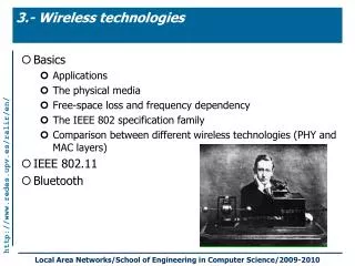
LAN Technologies • IEEE 802.3 Carrier Sense Multiple Access with Collision Detection (CSMA/CD), also known as the Ethernet: • 10 Mbit/s transmission speed and • Bus topology (shared medium). • IEEE 802.5 Token Ring: • 4 Mbit/s and 16 Mbit/s versions and • Ring topology (shared medium). • Distributed Medium Access Control Algorithm. • Universal cabling systems with star topology are suitable for both LANs (unshielded and shielded twisted pair).
802.1: LAN/MAN Bridging & Management (.1p, .1q) 802.2 Logical Link Control* 802.3 CSMA/CD Access Method (.3z, .3ab) 802.4 Token-Passing Bus* Access Method 802.5 Token Ring Access Method* 802.6 DQDB Access Method* 802.7 Broadband* 802.8 Fiber OpticU 802.9 Integrated Services / Isochronous LAN* 802.10: LAN/MAN Security* 802.11: Wireless LAN 802.12: Demand Priority Access Method* 802.13 n/a (!) 802.14: Cable ModemsU 802.15: Wireless Personal Area Networks 802.16: Broadband Wireless Access 802.17: Resilient Packet Rings (study group) IEEE 802 LAN Standards *: inactive; U:disbanded
CSMA/CD Medium Access Algorithm location Maximum throughput is roughly indirectly proportional to : /m = (C) / L : Propagation delay [s] m: Frame length [s] L: Frame length [bit] C: Transmission rate [bit/s] For good performance, should be <= 0.01. B’s frame B detects collision. A’s frame A detects collision. A sents jam signal. A recognizes busy medium. All stations know about the collision. A and B back-up for a randomized period of time. B sents jam signal. B retransmits the frame. time
Preamble: Bit synchronization SFD: Byte synchronization DA: Destination address SA: Source address Length: Length of payload Payload: Upper layer frame PAD: To fill up a short frame FCS: 32-Bit CRC for error detection CSMA/CD Frame Format 7 1 2 (6) 2 (6) 2 0...1500 4 Byte 46 Preamble SFD DA SA Length Payload PAD FCS
Hub Switch Switching (1) • Hubs vs. Switches: • Similar locations in networks. • Hubs repeat all packets while switches examine all of them. • Switches require address examination and forwarding. • Store-and-forward: Analyze the entire packet. • Cut-through: Only examine destination and forward. • Blocking vs. non-blocking architectures. • Buffering: backpressure or large buffers. B C D E B C D E F A F A to E to E
Switching (2) • Handle packets at wire speed. • Layer-2-Switching: • cf. before • Layer-3-Switching: • Combination of switching speed and router functionality. • Similar terminology: Routing switches or IP switches. • Identification for common traffic flows on layer 3 and switch these flows on the hardware level for speed. Other traffic will be routed as usual. • Layer-4-Switching: • Includes application-level control by applying filters, e.g., security, and QoS-control on specific application flows.
Fast Ethernet • 100 Mbit/s version of Ethernet, using CSMA/CD algorithm (recent addition to IEEE 802.3). • 10 times faster than “normal” Ethernet, and 10 times smaller (max. app. 200 m between stations). • Easy upgrade path from Ethernet, simply replace Ethernet hubs, adapters, and driver software! • Autosensing of physical media. • Works with several physical media:
Gigabit Ethernet • Marketing aspect: • Term Ethernet used to hint at easy and cheap upgrade, reliability. • Theory is different: • If CSMA/CD is used on a shared medium, the allowable size of a Gigabit Ethernet segment will be rather small (roughly 20 m). • If CSMA/CD is not used, it’s not Ethernet. • Realistically, a Gigabit/s LAN need not be a CSMA/CD-based LAN to grant compatibility. • Important are cost, compatibility with existing cabling and systems, and availability of good drivers for popular operating systems.
Gigabit Ethernet – Objectives • IEEE 802.3 commitee‘s key objectives: • Half- and full-duplex operation at 1000 Mbit/s. • Complying with IEEE 802.3 Ethernet frame format. • Applying CSMA/CD access method. • Allowing one repeater per physical collision domain. • Providing address compatibility with Ethernet and Fast Ethernet technologies. • Timelines: HigherSSG Interim Meeting PAR Approved 802.3z Approved First Plan Standard CFI HigherSSG Standard Approved First Draft Approved WG Ballot LMSC Ballot HSSG Formed PAR Drafted Year 1999 1995 1996 1997 1998 CFI: Call for Interest, PAR: Project Authorization Request, WG: Working Group, HSST: High-Speed Study Group
Preamble Start Frame Delimiter Destination Address Source Address Length/Type Data Padding Frame Check Sequence Extension 7 Byte 1 Byte 6 Byte 6 Byte 6 Byte 1518 Byte 0/1 Byte 4 Byte Transmission bit 0 bit 7 Gigabit Ethernet – Frames • Frames compatible withEthernet classic. • Preamble: 101010 … 10. • Start Delimiter: 10101011. • Padding: Even # of Bytes. • Extension used to safely detect collisions. • Bursts: Concatenation ofmax. 65536 Byte. MAC Frame/Extension Inter Frame MAC Frame Inter Frame MAC Frame Burst Limit
Gigabit Ethernet – Physical Layer • Symbols are used to code MAC data (802.3z): • 8B/10B coding scheme (8 bit user data/10 bit phy. data) • Code-inherent clock regeneration. • Always min 4 and max 7 state changes per symbol. • 1250 Mbaud. • Code group symbols (always different to data symbols): • Carrier Extension, • Idle, • Start-of-Packet, • End-of-Packet, • Configuration Marks, and • Violations.
Cabling Type Waves Distance Plugs 1000BASE-SX 1000BASE-SX 1000BASE-LX 1000BASE-LX 1000BASE-LX 1000BASE-CX 1000BASE-CX 1000BASE-T 62,5 µm Fiber 50,0 µm Fiber 62,5 µm Fiber 50,0 µm Fiber 10,0 µm Fiber STP IEC 61076 Multimode Multimode Multimode Multimode Monomode Twinax Twinax UTP, Cat 5 830 nm 830 nm 1270 nm 1270 nm 1270 nm 2 – 260 m 2 – 550 m 2 – 550 m 2 – 550 m 2 – 3000 m 25 m 25 m 100m Duplex SC Duplex SC Duplex SC Duplex SC Duplex SC DB9 (Style 1) IEC (Style 2) RJ-45 Gigabit Ethernet – Physical Media • Standard for UTP cabling accepted in June 1999 (802.3ab,1000BASE-T) • Smaller distances for fiber cabling compared to Fast Ethernet and FDDI due to dispersion.
Network Design (1) • Backbone • Backbone Switching(collapsed backbone) • Multiswitch Backbone • N-tiered Switch (N=2)
Network Design (2) • Workgroup Segmentation(decentralized) • Workgroup Segmentation(centralized) • Micro Segmentation
A B D A C B D C Token Ring Medium Access Algorithm Free token A B D C Newly generated free token Busy token Note: At 4 Mbit/s, one bit occupies 50 m of cable!
High Speed Token Ring (HSTR) – Objectives • IEEE 802.5 commitee‘s key objectives: • Support large Token Ring frames sizes (up to 18.2 kByte). • Full source routing support (RI field up to 14 hops). • Eight levels of priority. • Availability and robustness as with 4/16 Mbit/s versions. • Scaling from 100 Mbit/s up to 1 Gbit/s. • Upwards compatibility with 802.1q (multiple VLANs) • Timelines: Foundation of HSTRA First Products Technical Review Round Table, PAR Ideas Interoperability Tests 8 9 4 5 6 7 Year 1997 1998 PAR: Project Authorization Request HSTRA: High Speed Token Ring Alliance
HSTR – Members, Goals • High Speed Token Ring Alliance (HSTRA): • 3Com • Bay Networks • IBM • Madge Networks • Olicom • University of New Hampshire – Interoperability Lab • Xylan • Goals: • Minimize cost of acquisition and ownership. • Maximize throughput and utilization.
Press Coverage (1) • InternetWeekAugust 29, 1998 • With its high-speed network interface cards and uplinks, Olicom next week will become the first vendor to ship 100-megabit-per second token-ring devices. Olicom's RapidFire 3530 HSTR 100 peripheral component interconnect adapter and CrossFire 8650 HSTR uplink are part of what the company is calling a "renaissance" in token ring, said Jorgen Hog, vice president of product management. He said there's still a huge base of token-ring users that like its stability and can't afford to switch to technologies such as gigabit Ethernet
Press Coverage (2) Just A Token Presence?By David Wilby Network WeekNovember 18, 1998 (...) In one recent study, the Tolly Group concluded through testing of Olicom's CrossFire 8650 HSTR uplink and HSTR server adaptor, that the technology consistently delivered higher throughput and better use of CPU ratings than Fast Ethernet. Joergen Hoeg, vice-president, product marketing of Olicom duly asserted: These tests prove... that it [Token Ring] is a more efficient and robust networking technology than Ethernet. But surely it is now irrelevant for the majority of managers with purchasing power whether or not TR has any technical benefits over Ethernet? Determined HSTR vendors must now fight for the remaining TR sites, that have decided to stick with the devil they know, and save on the expense of ripping out their TR infrastructures and flood-wiring with Ethernet technologies. (...)
Press Coverage (3) Bell Tolls For High-Speed Token Ring AllianceBy Marc Songini Network WorldJuly 26, 1999 Roughly two years after it started, High-Speed Token Ring Alliance (HSTR) has accomplished its goals of establishing a specification and seeing some members ship 100M bit/sec token-ring products. The question is, does all of this activity matter? Has the HSTRA arrived just in time for its own funeral? Founded to give token-ring customers an upgrade alternative to 100M bit/sec Ethernet, the HSTRA's roster initially was a who's who of network players, including Cisco, 3Com, Texas Instruments, Compaq, Cabletron, Xylan, the former Bay Networks and IBM. Now after two years, the membership list has been whittled down, by defections or acquisitions, to the three leading token-ring players: IBM, Madge and Olicom. (…) Note: In September 1999, Olicom sold their TR business to Madge.
Press Coverage (4) • Raleigh, NCSeptember 27, 1999 • FROM: • Scott D. SmithVice President, Worldwide Sales and Marketing IBM Networking Hardware Division • TO: • All IBM Token Ring business partners and customers • In light of our recent announcement of an alliance with Cisco, and the concurrent announcement of the purchase of Olicom's Token-Ring business by Madge, I am writing to clarify our position and answer any questions you may have regarding IBM's commitment to providing you with Token-Ring products, solutions and support.Our new relationship with Cisco pertains only to our routing products and ATM and Ethernet switching offerings. It has no impact on our continuing development, enhancement and support of Token-Ring products. You will still be able to purchase all the IBM Token-Ring adapters, hubs and workgroup switches that you have in the past. We also will continue to enhance our Token-Ring portfolio as the market demands, with a significant product announcement planned for early next year. (…)
Fibre Channel: Goals • Performance 266 Mbit/s - 4 Gbit/s • Support for distances up to 10 km • High-bandwidth utilization with distance insensitivity • Broad availability (i.e., standard components) • Support for multiple cost/performance levels, from small systems to supercomputers • Ability to carry multiple existing interface command sets, including Internet Protocol (IP), SCSI, HIPPI-FP, and audio/video.
Fibre Channel Technology (1) • High speed serial links for processor-to-processor or processor-to-mass storage interconnectivity. • Point-to-point: High speed, “zero” latency, limited. • Switching fabrics: Virtual point-to-point links, connections must be set up through switch, 10µs latency. • Arbitrated loops: Shared capacity of one Fiber Channel between all nodes, low latency. • Fiber Channel layering: • FC-0: Physical issues: links, speed, cabling, distances. • FC-1: Block encoding method (8B/10B). • FC-2: Framing, service classes, fragmenting. • FC-3: Set of common services for higher-layer protocols. • FC-4: Mapping of higher-layer protocols onto FC services.
Fibre Channel High speed interconnect Processor to processor Processor to mass storage Point-to-point links All IEEE 802.1 service classes connectionless connection-oriented request-response Transports IP, SCSI Fast Ethernet Inexpensive, emerging technology. A 100 Mbit/s solution that integrates well into many installed Ethernet bridged and routed networks. Use of existing expertise – familiarity with Ethernet should enable customers to incorporate this new technology easily into their existing networks. Summary of High-speed Technologies • Gigabit Ethernet • Technology now stable. • Compatibility with UTP cabling. • Uses Ethernet frame formats. • Easy integration in an existing Ethernet switching infrastructure. • Attractive backbone technology. • „Ethernet“ label mainly a marketing asset.
Comparison Taken from http://www.fibrechannel.com/technology/technology.htm
References • Tutorial materials on: ATM, VG AnyLAN, Ethernet, Fast Ethernet, Fiber Channel, Gigabit Ethernet; http://www.iol.unh.edu/training/index.html • C. Spurgeon: Quick Reference Guide to 100 Mbps Ethernet; http://wwwhost.ots.utexas.edu/ethernet/descript-100quickref.html • IEEE Standards Library:http://standards.ieee.org/catalog/olis/index.html • Gigabit Ethernet Comes Of Age (A 3Com White Paper); http://www.3com.com/technology/tech_net/white_papers/503003.html
Part II: LAN Technologies and Internetworking • LAN Technologies • Switching • Ethernet • Token Ring and Fiber Channel • Multi Protocol Label Switching • Evolution • Architecture • Impacts on Network Management
IP Datagram based Backbones • Efficient longest prefix matching requires complex algorithms. Simple implementations are too slow for large backbones. • Each router maps IP packets to a “Forwarding Equivalence Class”. This requires large filter databases in every backbone router. • The IP routing paradigm does not provide adequate traffic control mechanims (load balancing, multi-path routing, ...).
Overlay Network Model ATM network appearsas single link between each router pair. ATM Network Router with ATM trunk port Router with ATM trunk port (Router solution initially used by SWITCH between Universities)
Assessment of the Overlay Model • Data forwarding in the backbone is very efficient. • VPCs allow for an explicit control of traffic flows. • VPCs require manual configuration. • For n peering routers, n2 VPCs or SVCs are needed. This limits the scalability of the approach. • If SVCs are used, routing is done in both the IP and the ATM layer. • Two independent networks have to be operated, managed and maintained.
IP Switching: Ipsilon’s Solution IP Software(Routing) ATM Signaling(Routing) IP Software(Routing) IP Data Link ATM Switching ATM Switching “The best of two worlds”
IP Switching Architecture • Ipsilon’s IP Switch Architecture: • Flows = IP packets with similar source and destination address. • Long living flows are supported by setting up an ATM connection. • Short livingflows are routed(layer 3). IP Switch Controller (IP Router) General SwitchManagement Protocol (GSMP) IP SwitchController IP SwitchController ATM-Switch Ipsilon FlowManagement Protocol(IFMP) ATM-Switch ATM-Switch
2. 1. 4. 3. VCI = X VCI = Y 5./6. Setup of an ATM Connection for Flows IP SwitchController IP SwitchController ATM-Switch ATM-Switch 1. Arrival of IP packet and forwarding via IP switch controller. 2. Switch controller decides on setup of an ATM connection. 3. Send re-configuration to upstream switch to use separate VPI/VCI. 4. Re-configuration message arrives at downstream switch. 5. Cut-through link is connected. 6. Cut-through link is disconnected, if configuration messages are missing.
Assessment of Ipsilon’s IP Switching • Data forwarding in the backbone is very efficient. • Architecture is homogeneous and fairly simple. • GSMP and IFMP are published as informational RFC 2297 and RFC 1953, respectively. • Scalability is limited due to a potentially large number of traffic flows. • Since path is only set up after a number of packets have been processed, a high latency results. • Requires high performance packet classifiers. • Only applicable to ATM networks. • Ipsilon has vanished from the market.
Multi-Protocol Label Switching • Ipsilon’s basic idea has triggered follow-up solutions: • Tag Switching [Cisco] • Cell Switch Router [Toshiba] • Aggregate Route Based IP Switch ARIS [IBM] • IPSOFACTO [NEC] • Standard is now being developed by the IETF. • Initial products are available. (see, e.g., http://www.dataconnection.com/mpls/mplsidx.htm)
MPLS overview • MPLS consists of two components: • Network independent forwarding component • Control component • Forwarding based on simple, fixed-sized labels • VPI/VCI for ATM • Small “shim” label header for native IPv4 networks • IPv6 flow label • Control component creates bindings between labels and routes using combinations of: • Layer-3 destination prefix, forwarding equivalence class (FEC) • IP “Class of Service” bits • Application flows • Explicit routing (configured by network manager)
MPLS Architecture Overview • Label Distribution Protocol • Distributes labels between devices • MPLS Edge Routers • Full-function layer-3 routers • Apply labels to packets • Run the Label Distribution Protocol and standard routing protocols • Label Switch Router • Forward packets based on labels • Run the Label Distribution Protocol and standard routing protocols Label DistributionProtocol (LDP) MPLS Edge Router Label SwitchRouter (LSR)
1 2 3 4 4 5 MPLS Operation 1) Standard Routing Protocol (OSPF, BGP, ...) used to establish routes in Edge Routers and Switches 2) Label Distribution Protocol builds up label bindings 3) Ingress label switch router “labels” packets 4) Label switches switch packets based on the label (no network layer needed) 5) Egress label switch router removes label from packets In label Address Prefix Out Interface Out label Example label bindings 129.132 1 1 4 2 171.56 2 8
Why Does MPLS Scale? • Multi-point to Point Tree(Merging of Label Switched Paths) • Traffic aggregation Access Network Backbone
Summary MPLS • Allows for high performance backbones with multi-gigabit/s links. • Suitable for large backbones due to multipoint-to-point trees and topology driven approach. • Offers a wide range of traffic control mechanism (topology-, request- or traffic driven, configured). • Can be used on different layer 2 network technologies (not just ATM). • MPLS Switching may soon be an IETF standard. • High flexibility may limit interoperability (motivation for interoperability tests/labs) • Per flow QoS is not feasible in MPLS.