Download
1 / 54
540 likes | 709 Vues
ECAL Design Studies and Scintillator/W/Silicon Hybrid. (Quite a lot of this talk overlaps with my (poor audio) talk from Dec 8 th – but there’s a fair amount of new material – and for several of you most of the material is new). Graham W. Wilson Univ. of Kansas Jan 8 th 2004.

E N D
ECAL Design Studies and Scintillator/W/Silicon Hybrid (Quite a lot of this talk overlaps with my (poor audio) talk from Dec 8th – but there’s a fair amount of new material – and for several of you most of the material is new). Graham W. Wilson Univ. of Kansas Jan 8th 2004
Optimize what ? I know that we are more interested in 2-particle separation than position resolution – but they are related. • Started looking mainly at EM energy resolution optimization in the context of BR2/RM maximization. • Have been looking in some detail at photon position resolution performance for various designs and pixel granularity • This wasn’t as trivial as I had anticipated. • So far, the studies reveal more questions to answer than answered questions. • Potential large changes in performance from new approaches. Comparing particular “baseline” designs may be premature. Graham W. Wilson
Rectangular Si pads (eg 2 mm X 10 mm) at start of shower W is expensive. Use W at front, Pb from 10 X0 on. (Pb int. length longer per X0). If correlations are useful, maybe even hybrid absorber plates ?? Progressive sampling Thicken up Silicon cf present 300 mm design (DS mentioned this last time) Staggering of layers of Si in ECAL to remove position bias Make hybrid readout units independent (improves dconv resolution & PATREC ?) Temporal calorimetry. (DT between photon and 1.5 GeV pTp is 0.6 ns for B=4T, R=1.7m) Recent ideas (some may be impractical) Many inspired by discussions before/during Montpellier (Numbers corrected after previous presentation.) Graham W. Wilson
Temporal calorimetry ? • For the same luminosity (L=2 10 34), the luminosity per bunch crossing is 1.6 times higher in warm cf cold. To some extent, event overlap scales directly with bunch crossing luminosity times no. of unresolvable bunches. • For warm with DTBX=1.4 ns, something like 300 ps time resolution required for bunch ID. With sT = 2 ns => say 15 bunches are consistent. • With bunch ID, event pileup : warm = 0.6 cold • With 2 ns timing, : warm = 10 cold • Integrate over bunch : warm = 120 cold => Precision timing is obviously an advantage if the LC technology is warm Graham W. Wilson
DT for 1.5 GeV pT tracks at cosq=0, for B=4.0 T, R=1.7 m pi : 0.59 ns K : 0.89 ns p : 1.68 ns DT for 3.0 GeV pT tracks at cosq=0, for B=4.0 T, R=1.7 m pi : 0.12 ns K : 0.19 ns p : 0.39 ns Temporal calorimetry for energy flow ? Idea: Use time difference between b=1 straight line (photon) and b<1 curved track (charged pi, K, p) Loopers have pT = 1.02 GeV here. Conclusion: of order 100 ps resolution needed for time differences of the primary particle to be useful => looks impractical Graham W. Wilson
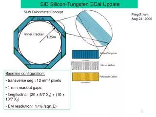
Energy resolution for sampling W calorimeters Si-W design (SLAC/Oregon) => cost and minimal RM require compromise on E resolution by minimizing Si area (30 layers) and (Si thickness (300 mm)) Scint-W design (Colorado) => inexpensive, more samples – but poorer granularity and larger RM Si-W-Scint. Hybrid (Kansas, K-State)=> thin Scint. layers, cheaper, more samples (incl. Si), retain granularity, keep RM small Photons GWW Graham W. Wilson
Compactness Upper curves, 1mm gap CALICE Pb WO4 Lower curves, no gap Also plotted: Asian, LCCAL(Pb) Need to minimise gaps, reduce space needed for fiber routing, by sharing fiber routing gaps among layers Assume 25% of scintillator thickness used for readout Graham W. Wilson
Energy resolution for sampling W calorimeters 42 layers = 2.5 mm W 56 layers = 1.75 mm W 75 layers = 1.4 mm W 135 layers = 0.78 mm W Photons Cost issues: W cost independent of thickness if rolled ? Si and scintillator scale as area, and can be more expensive if thinner. GWW Also plotted, CALICE, Asian, LCCAL, PbWO4 Graham W. Wilson
MIP response GEANT4.5.0.p01 Range cut = 0.1mm There is a rumor from J-C B that later versions don’t have Landau mip response ? (started looking at pion response as well – but suspect hadronic interactions not enabled …) Graham W. Wilson
Energy spectra in Silicon per layer David Strom was wondering whether the reason our G4 simulations with 0.1 mm range cut were giving better energy resolution was related to soft energy deposits. 2 MIP 1 MIP Graham W. Wilson
Energy spectra in Silicon per pixel These are the plots with energies per pixel : 2 MIP 1 MIP Graham W. Wilson
Soft particles / E resolution ? In December, I had shown that total energy deposits per layer < 1 MIP are not relevant to E-resolution discussion (the lower curve). Now with individual pixels, the conclusion is that thresholds down to 0.3 MIP needed MIP energy Graham W. Wilson
Note: different samples used, so resolutions differ within statistics Soft particles / E resolution ?Smaller pixels Graham W. Wilson
Dynamic range 1000 10 GeVg events 1000 1 GeVg events Getting geared up to look at dynamic range and noise issues vs pixel size for Si – should also do same thing for Scintillator. 36 100 GeVg events Graham W. Wilson
Plan to work on improving photon measurement, E-flow performance of various ECAL designs (not just SDjan03) Graham W. Wilson
Hybrid Si-W-Scint. Calorimeter • Kansas: G. Wilson, C. Hensel, E. Benavidez, D. Gallagher, J. Robbins, P. Baringer, A. Bean, D. Besson • Kansas-State: T. Bolton, E. von Toerne, … getting started Concept : Develop a cost-optimized ECAL with most of the advantages of the Si-W concept, but finer sampling, excellent time resolution and cost which permits placement at larger R. Acknowledge : Si-W R&D work, tile-HCAL R&D. Open to collaboration with interested parties : beam-tests needed to verify some of the novel features Graham W. Wilson
Scint. Thickness – critical parameter for small RM 1 GeV photon, 75 layers, 1.4 mm W Developments in tile-HCAL R&D, suggest light yields of 5 pe/mip/mm achievable with Silicon PMs – up to 20 pe/mip/mm with high QE devices. Light-yield does not look to be overly critical. Can probably live with straight fibers. Curves are for 2.5, 5,10,20, pe/mip/mm Graham W. Wilson
Design studies using GEANT4 with Eric Benavidez (sophomore) • All calorimeter designs have 30 X0 of W (105 mm) to ensure adequate longitudinal containment and a fair comparison. • GEANT4 studies are done primarily with 1 GeV photons (which are definitely longitudinally contained) so far. • “EM Showers are understood, therefore GEANT4 is correct” thought process, needs data reality checks Graham W. Wilson
Software organization • Documented at http://heplx3.phsx.ku.edu/~eric • Three major chronological functionality improvements • Level 0 : examples/…./TestEm3 “out of the box” • Basic checks of overall energy resolution for simple geometries • Level 1 : hybrid ECAL with two different active media. • GEANT4 output saved as AIDA compliant tuple • Can be analyzed with JAS, PAW etc. • Allows studies of combined energy performance and longitudinal segmentation studies. • Level 2 : pixelized ECAL • Add arbitrary transverse segmentation in each absorber • Allows studies of position resolution, clustering etc … N.Graf in contact with us re using this for similar Si-W specific studies. Graham W. Wilson
Three strawman hybrid designs Studied with GEANT4 (range cut = 0.1 mm) A super-layer (SL) Sc-W-Sc-W-Si-W-Sc-W-Sc-W HY75 (15 SL) HY135 (15 SL) HY42 (14 SL) In each case the Si layer is chosen as 400 mm Si + 2.0 mm G10 as in SDMar01 detector So far: study uniform sampling structures. Graham W. Wilson
1.4mm W plates 15 layers Si 60 layers of 1.5mm Scint. 4 layers ganged (30 pe/mip) ( if 5pe/mip/mm) 15 super-layers each with mip-detection 0.778mm W plates 15 layers Si 120 layers of 1mm Sc 8 layers ganged (40 pe/mip) 15 super-layers HY75 HY135 HY42 • 2.5 mm W plates • 14 layers Si • 28 layers of 2 mm Sc • 2 layers ganged (20 pe/mip) • 14 super-layers E res : 10.4%/E 7.7%/E 14.3%/E Moliere radius : 19.3 mm 21.4 mm 16.5 mm 33% of the Silicon cost (SDMar01 30X0 W : 15.4%/E, 15.5 mm) Graham W. Wilson
Complementarity - Correlations HY135 : 7.7% E-resolution Correlation improves resolution slightly – compensates for PE stats Correlation coefficient = -0.20 ± 0.01 Graham W. Wilson
Scintillator/Silicon Energy Correlation Coefficients Leads to small improvement in energy resolution over naïve expectations ! • HY75 : -0.16 ± 0.01 • HY135 : -0.20 ± 0.01 • HY42 : -0.15 ± 0.01 • Not understood exactly how the negative correlation arises. • Adjacent active materials have high positive correlation. • Initial +ve correlation gradually becomes –ve as all the energy in the shower is integrated longitudinally and unitarity sets in ? Graham W. Wilson
Correlation Plots Energy deposited in Sc and Si within each super-layer +vely correlated Total energy starts out with +ve correlation between Sc and Si but eventually becomes negative Graham W. Wilson
HY75 Silicon Energy in scintillator note tails G10 Tungsten Graham W. Wilson
Hybrid calorimetry ? • It could be that a novel choice of active detection media may allow an even stronger negative correlation. • Plan to study dependence on layer thicknesses, and play with ideas like lead-loaded scintillator. • It could be that some layers of neutron sensitive material could help the energy flow ? Graham W. Wilson
Tile-fiber response simulation • At Cornell – showed first studies of optical simulation. • Haven’t really followed up too much on this yet. • Obtained DETECT2000 program (C. Moisan et al.) for optics simulation (C++ version of DETECT – G. Knoll et al) for modelling optical properties of scintillators and reflective materials using “unified optical model”– and designing assemblies – lot more light-weight than GEANT4 – and tuned to real applications. So maybe DETECT is the better way to do the optical simulation. Graham W. Wilson
VME DAQ from scratch Using LabView 8 2” PMTs with help from K-State. 1st QDC & TDC measurements this Tuesday. Planning flexible testing capabilities of various scintillator/fiber geometries for light-yield, uniformity, time resolution. Cosmic ray test setup Nov 9th, 2003 V812 CFD V775 TDC (35ps LSB 12-bit) V792N QDC (100fC LSB 12-bit) Graham W. Wilson
QDC spectrum Fresh off the press Pedestal is 160, rms<1channel Graham W. Wilson
TDC spectrum Same signal as start and stop. RMS=50 ps. GOOD ! Not yet ready for prime time. Graham W. Wilson
Mechanical design work Jim Robbins working with us. EE with AutoCad experience 9 cm high 75 cm Stackable dark boxes for scintillator tiles in cosmic ray test setup => machine shop Diagram shows Photonis XP2020 PMTs. Graham W. Wilson
Transverse granularity for Si, Scint. tiles ? Shower profiles from OPAL Si-W. Plots suggest that scintillating tiles of reasonable dimensions by themselves will not do the job Scintillator-based sampling cost may be dominated by photo-detector channel count Graham W. Wilson RM = 15 mm
Transverse Segmentation d=2D • Standard lore : cell-size, d, should be of order the Moliere radius, RM • If d >> RM , very little energy sharing with adjacent cells => poor position resolution • If d << RM, many channels, diminishing returns • Have studied square pixel sizes of 50, 16, 5, 1 mm Graham W. Wilson
50 mm 1 GeV photon Regime of d >> RM is hard to deal with using standard ybar algorithm Graham W. Wilson
HY42 design (RM=16 mm) 1 GeV photons 50 mm 16 mm Pixel size 5 mm 1 mm yrec-ytrue (mm) Graham W. Wilson ytrue (mm)
1 GeV photons 50 mm s=10 mm 16 mm Pixel size s=3 mm 5 mm s=2 mm i.e. 2mm/E HY42 : using both Silicon and Scintillator. Silicon only about 50% worse. Graham W. Wilson
Position Resolution if we could have 1mm x 1mm pixels ! • Using Silicon energy weighted position estimates for 1 GeV photons • HY135 (RM=19.8 mm) spos = 2.7 mm • HY75 (RM=18.0 mm) spos = 2.5 mm • HY42 (RM=15.6 mm) spos = 2.2 mm • SI42a (RM=16.9 mm) spos = 2.0 mm • SI42b (RM=13.5 mm) spos = 1.5 mm 15 Si 15 Si 14 Si 42 Si 42 Si Graham W. Wilson
Superb Position Resolution for 1 GeV Photons For illustration purposes only !: Si-W, 42 layers, 1mm x 1mm pixels, RM = 13.5 mm First 10/7 X0 330 mm First 15/7 X0 380 mm 1 GeV photons Transverse segmentations much finer than 5 mm may be useful – Si strips ? Integrated 1500 mm Graham W. Wilson Position residual (mm)
Position resolution from simple fit Neglect layer 0 (albedo) Using the first 12 layers with hits with E>180 keV, combine the measured C of G from each layer using a least-squares fit (errors varying from 0.32mm to 4.4mm). Iteratively drop up to 5 layers in the “track fit”. C of G all layers s = 1.5 mm Weighted fit of the C of G found in the first 12 layers with hits Position resolution does indeed improve by a factor of 5 in a realistic 100% efficient algorithm! s = 0.30 mm Graham W. Wilson Still just d/12 !
Summary • Starting to grapple with some ECAL optimization degrees of freedom which are not yet fully appreciated. • The hybrid concept looks encouraging • There don’t seem to be unforeseen drawbacks of two active media – if anything advantages (-ve correlations) • The necessary thin scintillator layers appear feasible • Will soon be able to test this • By playing the strengths/weaknesses of Si vs Scint. (transverse granularity/cost/timing) against each other, we may design a better ECAL Graham W. Wilson
Backup Slides • (some of these are from Montpellier and not necessarily that relevant today) Graham W. Wilson
5mm pixels, 10 GeV photon Graham W. Wilson
Is superb photon position resolution useful? • High energy p0’s for sure. • Many jet channels have applicable kinematic constraints – angular resolution may be just as important as energy resolution • But neutral hadrons may dominate uncertainties Graham W. Wilson
How to move towards deciding among technologies/approaches ? • Need realistic cost models of various designs • The Pb or W decision seems almost entirely a matter of cost. • What metric to use for performance comparison ? • Also tied in with global detector design particularly, B-field, tracking quality, RECAL. Graham W. Wilson
ECAL Challenges Major challenges for each approach Si-W : thin active gaps, cost for acceptable R and E-resolution Sc-W : thin active gaps, granularity Crystals : long. segmentation hybrid : thin active gaps, cohabitation • Compact calorimeters with signals ! • Transverse segmentation to a fraction of the Moliere radius • Cost-effective yet high performance design • Sound mechanical design • Establishing accepted ways to evaluate high-level particle-flow like performance of different designs Graham W. Wilson
Estimating impact position of photons in a Cadillac ECAL • Don’t need to use longitudinally integrated cell energies. • Can try and identify the photon conversion and measure its position from nearby (in depth) energy deposits • Specialized shower max detector or photon conversion point finder… • Can offset pixels cancelling wiggles (to some extent). Colorado group have looked at this • I learned from J-C Brient yesterday that the position resolution estimate in the TDR assumed successive layers are staggered by 1 mm. Graham W. Wilson
Estimating impact position in projective calorimeters • Several Methods • Standard one. Form estimator ybar by energy weighting the cell centers. • Alternative. Modify estimator by giving more weight to the tails (eg. weight = E 0.45) • Shower fit. Adjust impact point to give best fit between measured cell energies and integrals of the average shower profile over each volume pixel • Use cell sharing function • All subject to bias • should be correctable at some level • but maybe at the expense of “resolution”. Graham W. Wilson
Wigmans HY42 Graham W. Wilson