Overview Multiplexing techniques Circuit switching
Multiplexing and Switching Technologies. Overview Multiplexing techniques Circuit switching Space Division (SDM) - Digital Cross Connect Frequency Division (FDM) Origins of packet switching Time Division (TDM) Introduction to: Addressing - Frame relay

Overview Multiplexing techniques Circuit switching
E N D
Presentation Transcript
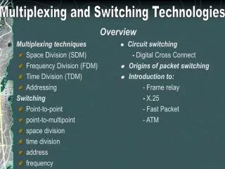
Multiplexing and Switching Technologies Overview • Multiplexing techniquesCircuit switching • Space Division (SDM) - Digital Cross Connect • Frequency Division (FDM) Origins of packet switching • Time Division (TDM) Introduction to: • Addressing - Frame relay • Switching - X.25 • Point-to-point - Fast Packet • point-to-multipoint - ATM • space division • time division • address • frequency
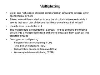
Multiplexing and Switching Technologies Multiplexing Technologies • Multiplexing defines the means by which multiple streams of information from multiple users share a common physical transmission medium all of which may require some or all of the bandwidth at any given time. • Switching takes multiple instances of a physical transmission medium, each containing multiplexed information streams, and rearranges the information streams between the input and output of the switch.
Multiplexing and Switching Technologies Multiplexer Defined • The multiplexing function shares many inputs to a single output. The demultiplexing function has one input which must be distributed to many outputs. • Refer to Figure 6.1 (p. 189) • The overall speed on the access side interfaces is generally less than that on the trunk side. • Multiplexing techniques can be used to share a physical medium between multiple users at two different sites over a private line with each pair of users requiring some or all of the bandwidth at any given time.
Multiplexing and Switching Technologies Multiplexing Methods Space Division Multiplexing • It can be facilitated by mechanical patch panels, or by optical and electronic patch panels • It is being replaced by space division switching or other types of multiplexing • An example of SDM is seen where multiple cables interconnect equipment.
Multiplexing and Switching Technologies Frequency Division Multiplexing (FDM) • Many analog conversations are multiplexed onto the same cable, or radio spectrum,by modulating each signal by a carrier frequency. • Refer to Figure 6.2 (p. 190) • FDM multiplexes 12 voice-grade, full-duplex channels into a single 48-kHz bandwidth group by translating each voiceband signal’s carrier frequency. • One variation of FDM is Wavelength Division Multiplexing (WDM) based on Fiber technology. • Refer to Figure 6.3 (p. 191)
Multiplexing and Switching Technologies Time Division Multiplexing (TDM) • TDM allows multiple users to share a digital transmission medium by using preallocated time slots. • Refer to Figure 6.4 (p. 193) • Time slots are dedicated to a single user, whether data is being transmitted or the user is idle. The same time slots are dedicated to the same user in the same order for every frame transmitted. • Different time slots are dedicated to different channel sources, such as voice channels, data, or video. • Multiplexer inputs can carry simultaneously asynchronous and synchronous data
Multiplexing and Switching Technologies Time Division Multiplexing (TDM) (Continue….) • All transmissions through multiplexers are point-to-point • A single T1 circuit can be configured for 24 to 196 allocated channels. • Each channel uses 64 kbps • Refer to Figure 6.5 (p. 194)
Multiplexing and Switching Technologies Address or Label Multiplexing • A common name for address multiplexing is Asynchronous Time Division Multiplexing (ATDM) • Examples: SNA, DECNET, X.25, Frame Relay, ATM • Statistical Time Division Multiplexing (STDM) dynamically assigns time slots only to users who need data transmission. • The net effect is an increase in overall throughput for users since time slots are “reserved” or dedicated to individual users. • Refer to Figure 6.6 (p. 194) • Concentrator is a type of block-oriented multiplexer. • Concentrators transmit blocks of information for each user as needed, adding an address to each block to identify the user.
Multiplexing and Switching Technologies Address or Label Multiplexing (Continue…) • Concentrators utilizing this technique are called Asynchronous Time Division Multiplexers (ATDMs). • The primary difference between concentrator and multiplexing is that concentrators have additional intelligence to understand the contents of the data being passed and can route the information streams based upon the data within them.
Multiplexing and Switching Technologies Types of Multiplexers • There are four types of multiplexers used in data network designs: • Access multiplexer • Network multiplexer • Drop-and-insert multiplexer • Aggregator multiplexor • Most forms of multiplexing are protocol-transparent and protocol-independent. • Refer to Figure 6.7 (p. 197)
Multiplexing and Switching Technologies Access or Channel Bank Multiplexers • They provide the first level of user access to the multiplexer network. These devices typically reside on the user or customer premises • They provide network access for a variety of user asynchronous and synchronous, low- and high-speed inputs including: Data telephone, LAN, Low-speed video, terminal. • Access multiplexers usually provide one or more T1 trunks to the next class of larger multiplexers, the backbone multiplexer.
Multiplexing and Switching Technologies Access or Channel Bank Multiplexers (continue…) • There are two versions: • Fractional T1 multiplexer • SubRate Data multiplexer • Refer to Figure 6.8 (p. 198) • Refer to Figure 6.9 (p. 199) • Both versions optimize the use of access trunks for multiple low-speed users.
Multiplexing and Switching Technologies Network Multiplexers • They support T1 on the access side and T3 or higher on the network side. • They offer larger capacity, reroute capability, and configuration capability • Private and public data transport network backbones are built using network multiplexers. • Refer to Figure 6.10 (p. 200)
Multiplexing and Switching Technologies Aggregator Multiplexers • They combine multiple T1 channels into higher-bandwidth pipes for transmission. • M12 Multiplexer: 4 DS1s to the rate of DS2 • M13 Multiplexer: 28 DS1s to the rate of DS3 • M23 Multiplexer: 7 DS2s to the rate of DS3 • M22 and M44 Multiplexers: configuration management and rerouting capability of 22 and 44 channels • MX3 Multiplexer: different combinations of DS1s and DS2s to the rate of DS3 • Note that syncrhonization of the aggregate circuits within many of these multiplexers is not supported by many vendors
Multiplexing and Switching Technologies Drop-and-Insert Multiplexer • They are special-purpose multiplexers designed to drop and insert low-speed channels in and out of a high-speed multiplexed channel like a T1. • Channel speeds dropped and inserted are typically 56 or 64kbps. Each DS0 is demultiplexed and remultiplexed for transmission. • Refer to Figure 6.12 (p. 202)
Multiplexing and Switching Technologies Switching Techniques Space Division Switching • It delivers a signal from one physical interface to another physical interface. • Classical space division switch fabrics have been built from electromechanical and electronic elements with the crosspoint function. • Refer to Figure 6.15 (p. 207)
Multiplexing and Switching Technologies Time Division Switching • The operation of current digital telephone switches may be viewed as being made up of an interconnected network of special-purpose computers called Time Division Switches (TDS). • The TDS is effectively a very special-purpose computer designed to operate at very high speeds. • Refer to Figure 6.16 (p. 208)
Multiplexing and Switching Technologies Address Switching • Address switching operates on a data stream in which data is organized into packets, each with a header and a payload. The header contains address information that is used in switching decisions at each node. • All possible connection topologies can be implemented: point-to-point, point-to-multipoint, multipoint-to-point, and multipoint-to-multipoint. • Refer to Figure 6.17 (p. 208)
Multiplexing and Switching Technologies Frequency/Wavelength Switching • It translates signals from one carrier frequency (wavelength) to another. • Currently Optical Fiber networks use this method • The optical end system nodes transmit on at least one wavelength and receive on at least one wavelength. The wavelengths for transmission and reception are currently tunable in a time frame on the order of milliseconds, with an objective of microseconds. • Refer to Figure 6.18 (p. 210)
Multiplexing and Switching Technologies The Matrix Switch • They provide a simplistic form of T1 multiplexing and offer the capability to switch ports similar to a cross-connect. • They are composed of a high-speed bus for connection between ports. • They are controlled and switched through a central network-management center, and can manage the entire network from a single point. • The drawback is the possibility of failure, which would bring down the entire network. • Refer to Figure 6.20 (p. 212)
Multiplexing and Switching Technologies Packet Switching Technologies • Packet-switching allows multiple users to share data-network facilities and bandwidth, rather than providing specific amounts of dedicated bandwidth to each user. • The traffic passed by packet-switched networks is “bursty” in nature, and therefore can be aggregated statistically to maximize the use of on-demand bandwidth resources. • Due to the connectionless characteristic of packet switching, the intelligence of the network nodes will route packets around failed links. • Quick interview of packet switching technologies • X.25 - Fast Packet • Frame relay - ATM
Multiplexing and Switching Technologies X.25 • Access speeds range up to 56 kbps • Contains error detection and correction • Connectionless service using connection-oriented virtual circuits • Good for time-insensitive data transmission but poor for connection- oriented and time-sensitive voice and video. • Employs a queuing scheme for buffering and transmission of data • Allows numerous virtual circuits on the same physical path, and can transport packet sizes up to 4,096 bytes • Permanent Virtual Circuits and Switched Virtual Circuits are supported. • Traffic can be prioritized • Old technology
Multiplexing and Switching Technologies Frame Relay • It is a connection-oriented service employing PVCs and SVCs. • Frames can vary in size and bandwidth • Multiple sessions can take place over a single physical circuit • It is only a transport service (no error control or correction) • It must be transmitted over reliable fiber-optic transmission media with low bit-error ratios
Multiplexing and Switching Technologies Fast Packet • It is not a defined standard, protocol, or service. • Fast packet is a backbone technology which combines attributes of both circuit switching and packet switching. • It can accommodate both delay-sensitive traffic as well as data traffic not affected by variable delay. • It offers low network delay and high network resources efficiency • It provides protocol transparency • Fast packet technologies typically use advanced fiber-optic transport media, such as T3 and SONET.
Multiplexing and Switching Technologies Asynchronous Transfer Mode (ATM) • ATM is another form of fast packet switching. • Fixed size packets called cells • It provides two types of connection: • Virtual channel • Virtual path • It allows for the transmission for data, voice, and video traffic simultaneously over high-bandwidth circuits. • Full dublex 155.52 Mbps • Asymmetrical transmission from subscriber to network at 155.52 Mbps in one direction and 622.08 Mbps in the other • Full-dublex 622.08 Mbps service.
Cisco Switching Technologies
Objectives • Describe layer-2 switching • Describe address learning in layer-2 Switches • Understand when a layer-2 switch will forward or filter a frame • Describe network loop problems in layer-2 switched networks • Describe the Spanning-Tree Protocol • List the LAN switch types and describe how they work with layer-2 switches
Layer-2 Switching • Hardware based • Provides the following: • Hardware-based bridging (MAC) • Wire speed • Low latency • Low cost
Layer-2 Switching • Limitations • Bridging vs LAN Switching • Three Switch Functions at Layer 2 • Address Learning
Layer-2 Switching • Forward/Filter Decisions • Broadcast & Multicast Frames • Loop Avoidance
Spanning-Tree Protocol (SPT) • Purpose • History
STP Operations • Function • How does it do this?
Selecting a Root Bridge • Process
Spanning-Tree Port States • Port states • Convergence
Selecting the Designated Port • Process
LAN Switch Types • Store and Forward • Cut-through • FragmentFree
Summary • Described layer-2 switching • Described address learning in layer-2 Switches • Stated when a layer-2 switch will forward or filter a frame • Described network loop problems in layer-2 switched networks • Described the Spanning-Tree Protocol • Listed the LAN switch types and describe how they work with layer-2 switches
Cisco Internet Protocol
Objectives • Describe the different classes of IP addresses • Perform subnetting for an internetwork • Configure IP address in an internetwork • Verify IP addresses and configuration
Process/Application Layer Protocols • Telnet • File Transfer Protocol (FTP) • Trivial File Transfer Protocol (TFTP) • Network File System (NFS) • Line Printer Daemon (LPD)
Process/Application Layer Protocols • X Window • Simple Network Management Protocol (SNMP) • Domain Name Service (DNS) • Dynamic Host Configuration Protocol (DHCP)
Host-to Host Layer Protocols • Purpose • Protocols • Transmission Control Protocol (TCP) • User Datagram Protocol (UDP)