Global Design Effort for ILC Accelerator - Achieving High Energy, Luminosity, and Cost Efficiency
390 likes | 483 Vues
The Global Design Effort focuses on developing a next-generation electron-positron Linear Collider with adjustable energy from 200 GeV to 500 GeV, high luminosity, and upgrade potential to 1 TeV. Key challenges include energy, luminosity, and cost efficiency, with detailed parameter specifications for optimal performance and flexibility. Major differences in design since 2006 address timing issues for the undulator positron source and beam path adjustments. The Parameter Plane establishes crucial operating parameters like beam power and bunch characteristics. Availability and energy upgrade paths are scrutinized for operational reliability and future scalability, balancing costs with performance. By addressing luminosity overhead and design trade-offs, the project aims for significant cost savings and improved operational efficiency.

Global Design Effort for ILC Accelerator - Achieving High Energy, Luminosity, and Cost Efficiency
E N D
Presentation Transcript
The Baseline Configuration Tor Raubenheimer GDE SLAC Global Design Effort
RDR Matrix • Matrix of Area Systems and Technical Systems to develop cost estimate • International representation in all working groups Global Design Effort
The ILC Accelerator • 2nd generation electron-positron Linear Collider • Parameter specification • Ecms adjustable from 200 – 500 GeV • Luminosity ∫Ldt = 500 fb-1 in 4 years • Ability to scan between 200 and 500 GeV • Energy stability and precision below 0.1% • Electron polarization of at least 80% • Options for electron-electron and g-g collisions • The machine must be upgradeable to 1 TeV • Three big challenges: energy, luminosity, and cost Global Design Effort
Schematic of the Baseline ~31 km 14 mr ML ~10 km (G = 31.5 MV/m) RTML ~1.6 km BDS 5 km 14 mr e+ undulator @ 150 GeV (~1.2 km) R = 1.1 km E = 5 GeV x2 not to scale Global Design Effort
Major Differences since April 2006 • Adopted a solution for the e+ timing problem • 1.2 km insert into e+ linac that adjusts the path length for the e+ DR injection for greatest flexibility • Also a ~100 m to adjust path length between two interaction regions and to allow fine tuning • Adopted a BDS with two 14 mrad crossing angle beamlines instead of 2 and 20 mrad • The 2 & 20 mrad solution was more technically challenging and costly (mainly due to difficulties with the 2 mrad extraction line) • Detectors are located at same z location Global Design Effort
Timing Issues L1 L2 L3 L4 • The undulator positron source makes timing harder • Positron bunches must be injected into empty buckets in the e+ damping rings • Most flexible option is to re-inject into empty bucket delay n ring turns • Present design is off by ~2.5 km add 1.2 km insert into e+ linac – also need flexibility for 2 IRs e- damping ring e+ damping rings IP e- linac e- linac e+ linac e- source e+ source snapshot of bunch positions Global Design Effort
Parameter Plane • Parameter plane established • TESLA designed for 3.4e34 but had a very narrow operating range • Designed for single operating point • ILC luminosity of 2e34 over a wide range of operating parameters • Bunch length between 500 and 150 um • Bunch charge between 2e10 and 1e10 • Number of bunches between ~1000 and ~6000 • Significant flexibility in damping ring fill patterns • Vary rf pulse length • Change linac currents • Beam power between ~5 and 11 MW • Thought to have small cost impact – to be checked Global Design Effort
Example Parameter Sets Parameter range established to allow operating optimization Global Design Effort
Luminosity Overhead • Concern that the design has 2.5x L overhead • Linear colliders have limited operating space • Many parameters are already at the limit • Beam power, gradient, DR emittances, … • Additional parameter space is primarily gained by focusing harder • Requires shorter IP bunch lengths or causes a large increase in IP disruption some cost impact in BC • High luminosity parameters push everything to the design limit – unlikely to achieve L • Beamstrahlung increases and degrades luminosity cleanliness while complicating BDS operation • Significant cost savings in low Power design Global Design Effort
Energy Upgrade Path • Linac energy upgrade path based on empty tunnels hard to ‘sell’ • Empty tunnels obvious cost reduction • Lower initial gradient increases capital costs • Baseline has tunnels for 500 GeV cms with a linac gradient of 31.5 MV/m • Geometry of beam delivery system adequate for 1 TeV cms • Require extending linac tunnels past damping rings, adding transport lines, and moving turn-around ~50 km site Global Design Effort
Availability Issues • ILC is ~10x larger than previous accelerators • Developed availability monte carlo AvailSim • Working to compare against operating acc. • Predict very little integrated luminosity using standard accelerator MTBFs and MTTRs • Stringent requirements on component and sub-system availability • Improvements ~10x on magnets, PS, kickers, etc • Drives choices of redundant sources (dual electron source & backup positron source) and dual linac tunnels • Large impact on project and cost – needs further study Global Design Effort
Main Linac • Main features: • Gradient of 31.5 MV/m • Qualify cavities at 35 MV/m in vertical tests • ~5% overhead for variation in installed cryomodules • ~5% overhead for operations (1~2 MV/m below quench) • Packing fraction ~70% • Based on Type-IV cryomodule • Shorter cavity-cavity spacing (1.2l vs 3l/2) • Quadrupole in center of cryomodule • Type-III cryomodules installing in TTF • Rf power for 35 MV/m • 9.5 mA average current • 3% additional rf units for repair & feedback Global Design Effort
Main Linac RF Unit 8 Global Design Effort
Conceptual View of Dual Tunnel • Three RF/cable penetrations every rf unit (0.5 m) • Safety crossovers every 500 m • 34 kV power distribution Global Design Effort
Modulators & Klystrons • Baseline is the Fermilab/PPT bouncer modulator • Extensive studies on alternate options inc. compact Marx Generator • Better in terms of space, efficiency, cost, and availability • Baseline klystron is 10 MW MBK • Thales tubes appear to have lifetime problems when operating at full spec (4 tubes produced) • CPI tube tested to 10 MW but then operated at DESY at 8.3 MW and had vacuum failure • Toshiba tube has been running at full spec for ~1000 hours Global Design Effort
RF Distribution System • Complicated RF distribution • Many paths for optimization Global Design Effort
Cavity Gradient Choice • Balance between cost per unit length of linac, the available technology, and the cryogenic costs • Optimum is fairly flatand depends on detailsof technology • Current cavities haveoptimum around 25 MV/m Relative Linac Costs (from USTOS estimate) Gradient MV/m Global Design Effort
Baseline Main Linac Tunnel • Looking at smaller diameter tunnels to reduce costs Global Design Effort
Single Tunnel Option • Considereda singletunnel option • Small net savings • Need to add linacto recoveravailability • Need additionalshielding for electronics Global Design Effort
Main Linac Issues • Gradient choice • 35 MV/m demonstrated – work on fabrication process • RF klystron • 10 MW tubes demonstrated – work on improving lifetime • RF distribution • Large system with many components – cost optimize • Cryosystem • Segmentation at 2.5 km – some desire to reduce this • Machine protection system • Not clearly defined • Diagnostic sections and instrumentation • No diagnostics sections in linac Global Design Effort
Polarized Electron Source • Polarized electron source based on: • Polarized DC gun at 120 kV • Sub-harmonic buncher system • 70 MeV normal conducting linac • Energy and emittance diagnostics • 5 GeV superconducting linac • Spin rotator • Energy compressor • Diagnostics and beam dump • System is well defined • R&D needed to improve cathode lifetime and develop laser but relatively straight-forward Global Design Effort
Electron Source Dogleg SC Linac (84 MeV – 5 GeV) eLTR Emittance Meas. Spin Rotation Energy Compression Global Design Effort
Undulator Positron Source Beam Delivery System Positron Linac IP 150 GeV 100 GeV 250 GeV Helical Undulator In By-Pass Line Photon Collimators e- Dump e- Dump Photon Dump e- DR e- source e+ pre-accelerator ~5GeV Photon Target Adiabatic Matching Device Auxiliary e- Source e+ DR Adiabatic Matching Device e- Target • Undulator-based positron source • 150 meter undulator with K=1; l = 1cm; >6mm aperture • Two e+ production stations including 10% keep alive • Provides beam for instrumentation and feedback systems • Keep alive auxiliary source is e+ side • Better availability and possibly easier commissioning Global Design Effort
Positron Target • Large positron flux required • Large diameter Ti target wheel rotated at 500 rpm • Limited lifetime due to radiation damage • Remote handling probably needed • Immersion in 6~7T AMD field can improve yield by ~50% • Requires R&D to understand target/AMD issues Global Design Effort
Positron Source Optics pBSTR Trombone pBSTR Start of LTR pCAPA + pPA + pPATEL Trombone pTRAN bypass pLTR pLTR exit (90.66 m offset horizontally) • ~20 km transport large aperture line • Bypass aroundBDS • ~1.2 km delayto adjust timingfor DR injection • Trombone toadjust timing forseparated IPsand fine tuning 2 m vertical offset Global Design Effort
Positron Source Issues • Positron system design is coupled to linac and BDS design • Present layout minimizes conflicts but costs $ • Timing issues are a difficult constraint • Either severely constrain path lengths or limit flexibility – discuss in damping ring section • E+ emittance requires very large apertures • Long transport is expensive and may have problems with beam loss • Looking at centralized injector • Significant potential cost savings Global Design Effort
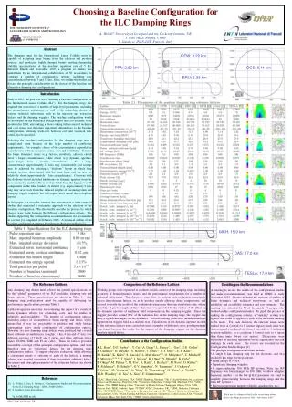
Damping Ring Requirements • Compress 1 ms linac bunch train in to a “reasonable size” ring • Fast kicker (ns) • Damping of gx,y=10-2 m-rad positron beams to (gx, gv)=(8 10-6, 2 10-8) m-rad • Low emittance, diagnostics • Cycle time 0.2 sec (5 Hz rep rate) = 25 ms • Damping wiggler • 2820 bunches, 21010 electrons or positrons per bunch, bunch length= 6 mm • Instabilities (classical, electron cloud, fast ion) • Beam power > 220 kW • Injection efficiency, dynamic aperture Global Design Effort
Damping Ring Layout • 6.7 km rings with 6 straights • 4 for wigglers and RF • Can operate with 3 RF stations • Injection/extractionis not fully designed • Arcs are ~20 TMEcells in 4m tunnel • Baseline has 2 e+rings to reduce ECI • Pursuing single e+ ring • Developing ‘centralized’injector with e+ & e- in same tunnel Global Design Effort
Damping Ring Parameters (1) • Baseline had 2x6.7 km e+ rings to avoid the electron cloud instability simulations with clearing electrodes suggests that a single e+ ring will be sufficient Global Design Effort
Damping Ring Parameters (2) • 6.7 km rings with 650 MHz rf frequency will support all parameter options • Superconducting wiggler parameters are similar to those demonstrated at CESR Global Design Effort
Electron Cloud Instability • Simulations indicate that problem is difficult in magnets – need SEY ~1.2 • Use solenoids in straights • Use electrodes/grooves in the magnets Global Design Effort
Ring To Main Linac • Dual stage BC • Pre-linac collimation • 180° for feed-forward • Diagnostics & tune-up dumps Global Design Effort
Vancouver Beam Delivery System • Vancouver Baseline • Two BDSs, 20/2 mrad, 2 detectors, 2 longitudinally separated IR halls • Present Baseline • Two BDSs, 14/14 mrad, 2 detectors in single IR hall @ Z=0 • Alternative #2 • Single IR/BDS, collider hall long enough for two push-pull detectors Global Design Effort
Vancouver BDS Cost Estimates • Additional costs for 2 mrad BDS • Extraction line significantly more difficult Global Design Effort
Detector Hall Layout 2/20 mrad Global Design Effort
2 mrad and 20 mrad IRs • Small separation of extraction and incoming beams in 2 mrad case • Complicated magnets • Backscattered radiation in IR • Long extraction with larger apertures • Higher cost and more technically difficult • 20 mrad based on compact SC quadrupoles developed at Brookhaven • Technology works down to ~14 mrad crossing • Physics impact of 14 mrad vs 2 mrad is small • Design well studied and developed Global Design Effort
Present 14/14 mrad Layout Global Design Effort
Studies Since Vancouver • Effort has been focused on cost • Understand the present cost estimates • Review the Technical System costs • Consider scope/layout for cost reduction • Major scope/layout considerations • Centralized injector complex • Single stage BC and other RTML options • Undulator vs conventional e+ source • Lower current linac operation • One vs Two linac tunnels • Beam Delivery System options Global Design Effort
Summary • Baseline configuration is well thought out • Based on decades of R&D • Technology reasonable extrapolation of the R&D status • Inclusion of availability and operational considerations • Conservative choices (for the most part) to facilitate rapid cost evaluation • Made a 1st pass at the cost estimate for Vancouver • Investigating a number of improvements post-Vancouver • Will need additional work on cost reduction • Component optimization as well as the sub-systems • Working on procedures for this Global Design Effort