Download
1 / 47
520 likes | 931 Vues
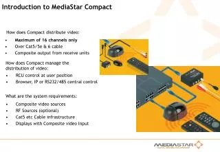
Introduction to MediaStar Compact. How does Compact distribute video:. Maximum of 16 channels only Over Cat5/5e & 6 cable Composite output from receive units. How does Compact manage the distribution of video:. RCU control at user position Browser, IP or RS232/485 central control.

E N D
Introduction to MediaStar Compact How does Compact distribute video: • Maximum of 16 channels only • Over Cat5/5e & 6 cable • Composite output from receive units How does Compact manage the distribution of video: • RCU control at user position • Browser, IP or RS232/485 central control What are the system requirements: • Composite video sources • RF Sources (optional) • Cat5 etc Cable infrastructure • Displays with Composite video Input
Compact – Connectivity RF Input MediaStar Compact Video Hub Remote Transmitter Unit A/V Cable A/V Cable I/R Blaster Cat5 Structured Cabling I/R Blaster DVD Unit Satellite Decoder Unit Display Duplicate Display DVD Unit RCU Receive Unit Recieve Unit I/R Receiver MediaStar Compact RCU Satellite Decoder Unit RCU
Hub Details Versions: 740 MediaStar Compact Video Hub supporting 16 users,16 Composite channel inputs,IR routing 743 MediaStar Compact Video Hub supporting 16 users,16 Composite channel inputs,IR routing and 2 x 4 Duplicate output capability and 8 Remote Video inputs Versions: R indicates a system with an RF tuner board installed
MediaStar Compact Video Hub – Fascia and backplane 8/16 4/12 5/13 6/14 7/15 DUPLICATE OUTPUTS of A/E 1/9 2/10 3/11 DUPLICATE OUTPUTS of A RF INPUT CHANNELS REMOTE INPUT CHANNELS POWER Video Hub VIDEO OUTPUTS A-P 1 – 8 9 - 16 A B C D E F G H I J K L M N O P Star M edia ompact c • 743 Compact VideoHub only • 8 remote video feed RJ45 Input sockets, options are: • Set as channels 9-16 (default) • Set as channels 1-8 • 743 Compact Video Hub only • 8 duplicate RJ45 Output sockets, options are: • All 8 duplicate of outlet A • 4 duplicates of outlet A and 4 duplicates of E Power LED Input configuration LEDs 16 RJ45 Output sockets labelled “A” to “P” Power Input RF Input (if fitted) Local video source inputs Serial Link IR Links IP Link Multiple Hub Link V-Bus and comms connectors PAL/NTSC Switch Spare Fuse
MediaStar Compact Video Hub – Rackmounting Fused 250V 2A ANTI-SURGE (T) 100-240 V Rack Mounting The MediaStar Compact Video Hub is supplied with 19” rackmount brackets. Once the rack mounting brackets are fitted, mount the Hub into the cabinet or closet using the screws supplied with the Rack Mount Kit Power connection Once the Hub is mounted in the cabinet, connect the Hub to an AC power supply using the IEC Power Lead supplied Once the lead is connected the Hub will power on automatically
Video format selection 1 PAL IR DRIVE 9 RF IN V-BUS NTSC • Set the video format required, PAL or NTSC, depending on your video sources • The switch can be found at the rear of the Hub, located next to the 64 V-Bus Connector • PAL = Upper position, NTSC = Lower position
Local video sources MediaStar Compact Video Hub A/V Cable Display Cat5 Structured Cabling I/R Receiver Recieve Unit Local A/V source MediaStar Compact RCU • Across the back of the Compact Video Hub is a bank of phono RCA connectors labelled 1 to 16 • For each local video source, the audio and video connectors must be plugged into the appropriate connectors on the hub • The source will appear on the channel as labelled by the video input connector (1 to 16)
Connecting local video sources 2 1 2 1 2 1 • Connect the source video device to the relevant audio and video inputs located at the rear of the Compact Video Hub • The video input is at the top (yellow), with the left audio connector in the middle (white) and the right audio connector at the bottom (red) • Ensure that the correct left and right audio feeds are connected
Connecting local video sources – 2 Channel example Satellite Decoder Dish input R IN VIDEO L R RF Output OUT L IN VIDEO DVD R Compact Video Hub The example below shows two video sources, a DVD and Satellite decoder unit, connected to the Compact Video Hub. Input 1 Input 2 • The DVD unit is connected to input 1 and will appear to users as channel 1 • The Satellite Decoder is connected to input 2 and will appear to users as channel 2 • The channel name displayed to the user can be edited
Local video source IR routing Versions: 911-4147 IR blaster Some TV channel sources (Satellite Decoder, DVD, etc) can be controlled using infrared remote control units. The IR routing feature of the MediaStar Compact System allows users to control these devices using the devices own RCU at the Compact Receive Unit position. A/V Cable MediaStar Compact Video Hub MediaStar Compact RCU Display I/R Blaster I/R Receiver Local A/V source RCU Cat5 Structured Cabling Local A/V source RX Unit • When the user selects a Compact TV channel, an IR ‘path’ is set up between the receiver in the Recieve unit and the TV channel source • The IR blaster module (part no.911-4147) itself is positioned over the IR receiver on the remote channel source device and connected to the Compact Video Hub via IR blaster drive connectors located at the rear of the hub • There are a total of 16 IR blaster connectors available, one for each input available • Note: the Compact Video Hub is supplied with 1off 911-4147 Blaster module
Connecting a local video IR source Satellite Decoder DVD Compact Video Hub This example shows two video sources, a DVD and Satellite decoder unit and their respective IR routing, connected to the Compact Video Hub. If the local or remote video source unit can be controlled with a 38KHz modulated IR remote control, an IR blaster is connected to the 2 pin polarised IR blaster connector on the backplane of the hub to the devices IR source. Note: Some IR control equipment uses different modulation techniques or frequencies and cannot be controlled through the MediaStar Compact System. • The IR blaster head must be carefully fitted over the video source unit’s own IR receiver • Care must be taken to ensure that the adhesive pad on the IR blaster head does not damage the surface of the unit • If the video source unit responds to IR commands intermittently, or does not respond at all, the power of the IR emitted by the blaster may need to be adjusted • Power is adjusted by turning the small screw on the outward facing side of the IR blaster
751 Video Receive Unit On the front of the Compact Video Hub there are 16 RJ45 sockets, labelled ‘A’ to ‘P’. The Video Receiver Units (part no. 751) are connected to these outlets with up to 400m of Category5 cabling. The users connected to these outlets are able to independently select any one of the 16 channels available. Versions: 751 Receive Unit Remote IR Receiver Socket Power/IR Receive LED V ideo Network Co n nection Video Adjustment L Video Video Adj Adj S Video Video IR IR Network Network Recvr Recvr A/V Output Underside view Front view Rear view C a ble • The Audio/Video (A/V) output cable provides the video signal and left and right audio signals to the TV, plasma display or PC graphics card on male phono connectors. • The Video Adjustment control should be set to provide optimum video picture quality. This can be done by viewing the picture or using video test equipment as required.
790/1X Remote Control • The 751 Receive unit is not supplied with the 751 Receive Unit and needs to be ordered separately. • You will need the Remote Control Unit to: • Change Compact channels • Change volume • Access on-screen information and menu options Versions: 790/1X Receive Unit
IR Receiver An integrated IR receiver is located at the front of the MediaStar Video Receiver Unit. When the unit receives any IR command from the Compact remote control unit (RCU), the LED on the unit will flash. Compact RCU Compact Video Hub Video Receiver Unit Remote IR Receiver • If the MediaStar Compact Video Receiver Unit is to be positioned where the IR receiver will not be visible, a remote IR receiver module (part no.911-4141) can be plugged into the Remote IR Receiver connector. • This can then be positioned discretely on the display unit, visible to the remote control unit. • The internal IR receiver in the Video Receiver Unit will be disabled. • When positioning a remote IR receiver, ensure that the surface where it is located will not be affected by the adhesive on the IR receiver.
Configuring Hub details • Using the MediaStar Compact IR remote control unit you can configure several • different settings on the Compact Video Hub, these include: • View current settings • Information given includes hub name, outlet label, software version, TV standard and channel input sources • Compact Video Hub name • Change the current hub name, default is “Video Hub 1” • Channels names • Set the displayed name for specific channels • Set New Password • Change the current password required to access the configuration options, default is “000000” • Define Duplicate Outlet Source • Define whether the second set of four duplicated outlets are duplicates of Outlet A or Outlet E, select Menu/Settings/Duplicate Source • Define Tuner Settings • Where internal tuners are fitted in the hub, the type of RF input into the hub must be defined. The channel and frequency for each tuner must then be defined
Configuring Hub details (continued) • Define Serial Comms Mode • If the hub is to be controlled by an external unit using the serial comms port, the mode of communication must be set up. • Set IP Details • In order to communicate with the hub over a 10BaseT LAN, the network IP settings must be configured. • Set Screen Background Colour • Use this option to change the background colour of the screen used for menus, select Menu/Settings/Screen Colour. • Set Channel Access • User access can be restricted to specific channels Please consult the MediaStar Compact User Guide for further details.
Category 5 Cable connectivity for 751 Units Pair RJ45 Pins 568B Colour Spec. Usage 1 4&5 Blue & Blue/White Audio Left/+12V 2 1&2 White/Orange & Orange Audio Right/-12V 3 3&6 White/Green & Green Communications/IR & Grd 4 7&8 White/Brown & Brown Video Downstream Typical RJ45 Pin 8 Pin 1 The MediaStar Compact system uses the Cat5 4pair structured cabling for the transmission of composite video/audio streams and control signals to individual users. • The maximum distance from Hub to user location must not exceed 400 metres (1200 feet) for Cat 5 UTP.
764 Compact-Evolution Interface Unit This unit provides an interface between the MediaStar Evolution DVI Endpoint and a MediaStar Compact TV distribution system. It takes a standard Compact TV feed and converts it to a format that can be input into the MediaStar Evolution Endpoint. The Evolution Endpoint can then use the Compact video and audio signals as a TV source that can be scaled and presented on any of the Endpoint’s output options. Versions: 764 Interface Unit Compact Video Hub Cat5 Structured Cabling Display I/R Receiver Evolution 760 or 760/xM Endpoint with 764 Interface Unit fitted Compact RCU • The Compact 751 Receive Unit in NOT required as the feed from the Compact Hub connects directly to the Interface Unit
753 RS232 to IR Converter Versions: 753 RS232 to IR Converter • The RS232 To IR Adapter (part no.753) provides a serial control • interface for MediaStar Compact Video Receiver Units. • Cabletime provides the Mediastar Viewer PC based software application that works with this converter unit to control the selection of TV channels. • You can, if you wish to use your own hardware or software for channel control. • This unit is powered from the Video Receiver Unit or Micro Settop, and requires no external power supply. The RS232 To IR converter is connected between an asynchronous serial communications port (typically COM1 on a PC) and the Remote IR Receiver socket of the Video Receiver Unit or Micro Settop unit. When the converter receives a specific ASCII character followed by a carriage return (<CR>), it transmits a series of electrical pulses into the Video Receiver Unit or Micro Settop unit. These pulses imitate the output from a Remote IR receiver when it sees IR from an RCU key press. The Video Receiver Unit or Micro Settop then responds to those RCU key presses in the usual way. • The serial interface operates using half duplex asynchronous serial communications, at 9600 Baud, with 1 start bit, 8 data bits, and 1 stop bit. There is no hardware handshaking. • On the 9 way D connector, pin 2 is RX data, Pin 3 is TX data and pin 5 is signal ground. • All other pins are not connected.
Compact Viewer As well as controlling the MediaStar Compact System with a Remote Control Unit (RCU), you can control it from a PC, using the MediaStar Compact Viewer software application. • The application allows PC users to select the channel to view, and adjust the volume setting. • It also provides access to all the on-screen setup menus that can be shown on a TV screen. • The Viewer application requires video hardware that has the relevant “Video for Windows” drivers. • Multiple copies of the Viewer application can be run simultaneously on a Desktop to enable control of several display devices. • If the user wishes to create their own control application for the Video Receiver Unit, the serial communications protocol for the Mediastar RS232 to IR converter is available. Please consult the MediaStar Compact User Guide for further details.
RS232 to IR Converter switch closure inputs 753 9 way D Type Female Connector 1 9 Button Channel Up 1 9 Button Channel Down Optional PC Serial 9 way D Connector This RS232 to IR Converter unit has four switch contact inputs to support external Channel up/down and Volume up/down keypads. • The switch inputs are on 4 pins of the 753’s 9 way D connector (see table below) • When a switch contact closure is made, the appropriate input pin should be shorted to pin 5 (ground) of the 9 way D connector • Switches must be of the ‘normally open’ type. If a switch (button) is held closed (pressed), the button press will auto-repeat after a short pause • Only one button should be pressed at a time. If more than one button is pressed, all buttons will be ignored • If a suitable 9 way D lead is produced, this unit can accept serial commands from a control system and switch closure inputs at the same time • If these switch inputs are not required, the unit can be connected to a computer using the supplied 9-way cable as usual Function pin Channel Up (U) 8 Channel Down (D) 1 Volume Up (+) 9 Volume down (-) 6 Signal ground 5 Serial TX 2 Serial RX 3 Example
IR Converter Connectivity options Audio & Video Lead 751 Video Receiver Unit Compact Video Hub 753 Converter Display Wall mounted touch panel Cat 5 Structured Cabling 753 Converter Connected to COM1 PC Running MediaStar Compact Viewer 751 Video Receiver Unit Audio & Video Lead Video Capture and Audio Cards
Duplicate outputs (743 Compact Video Hub Only) 743 MediaStar Compact Video Hub Duplicate Display 8 Cat5 Structured Cabling Duplicate Display 4 Display, outlet A RX Unit RX Unit • The Duplicate outlets consist of two groups of 4 RJ45 Sockets (743 Hub versions only) • The left group of 4 sockets are duplicates of Outlet A • The right group of 4 sockets can be configured via setup menus to be duplicates of Outlet A or all duplicates of Outlet E • This provides either 2 groups of 5 identical outputs or 1 group of 9 identical outlets • Any Video Receiver Units connected to Duplicated Outlets are able to make channel changes • Any channel change made will affect all the outlets that have been grouped together, including Outlet A or Outlet E
Remote video sources (743 Compact Video Hub Only) 743 Compact Video Hub Remote Transmitter Unit A/V Cable Cat5 Structured Cabling Remote A/V Source • Up to 8 remote video sources can be connected via CAT5 cabling to the hub (743 Hub versions only) using the remote video inputs located on the front of the hub • The maximum distance from the Transmit Unit to the Hub via Cat5 cable is 400 meters • Although hubs are fitted with 8 remote video inputs, any unused (unconnected) remote input may be used for rear panel local video inputs
Remote video source IR routing (743 Compact Video Hub Only) If the video source unit can be controlled with a 38KHz modulated IR remote control, an IR blaster is connected to the 2 pin polarised IR blaster connector on the Remote Video Transmitter. A/V Cable Remote Transmitter Unit 743 Compact Video Hub Note: Some IR control equipment uses different modulation techniques or frequencies and cannot be controlled through the MediaStar Compact System. Remote A/V source Cat5 Structured Cabling IR Blaster • Ensure IR blaster head is then carefully fitted over the • video source unit’s own IR receiver. • Ensure care is taken to ensure that the adhesive pad on the • IR blaster head does not damage the surface of the unit. • If the video source unit responds to IR commands • intermittently, or does not respond at all, the power of the IR emitted by the blaster may need to be adjusted. • The power is adjusted by turning the small screw on the outward facing side of the IR blaster head Display Receive Unit Remote A/V source RCU MediaStar Compact RCU
752 Remote Transmitter Unit (743 Compact Video Hub Only) Video Network L Video Left audio Right audio Video Adj Left Audio Input Power S Video Adjustment Video Input Right Audio Input IR Blaster Socket The Remote Video Transmitter (part no.752) is connected to the 743 Compact Video Hub via the CAT5 structured wiring system (up to 400m away). • The transmitter is powered from the hub • The LED will show orange when it is connected • The A/V sources are connected to the phono inputs on the transmitter unit • When a video input signal is detected, the Remote Video Transmitter LED will show green RJ45 Video Network Connection Power/Video Input LED Versions: 752 Remote Transmitter Unit • The video adjustment screw on the Remote Video Transmitter is turned to give the best picture quality
Category 5 Cable connectivity for 752 Units Pair RJ45 Pins 568B Colour Spec. Usage 1 4&5 Blue & Blue/White Audio Left/+12V 2 1&2 White/Orange & Orange Audio Right/-12V 3 3&6 White/Green & Green Communications/IR & Grd 4 7&8 White/Brown & Brown Video Downstream Typical RJ45 Pin 8 Pin 1 The MediaStar Compact system uses the Cat5 4pair structured cabling for the transmission of composite video/audio streams and control signals remote transmitters. • The maximum distance from Hub to remote location must not exceed 400 meters (1200 feet) for Cat 5 UTP.
Connecting an RF feed RF Connector If your MediaStar Compact Video Hub is fitted with a tuner module (R Suffix), up to 8 off-air or CATV RF sources can be used by the hub. Although hubs are fitted with blocks of 8 tuners, any unused (switched off) tuner source channels may be used for local video inputs instead. • The RF feed is connected via an ‘F’ type connector located on the rear face of the unit • The MediaStar Compact Video Hub tuner module supports PAL or NTSC standards • The MediaStar Compact Video Hub tuner module supports a frequency Range of 48 to 862MHz Configuring Where RF tuners are fitted in the hub, you must use the remote control unit or IP Browser interface to define RF input levels and tuner frequency settings.
Defining Input Settings 8/16 5/13 7/15 6/14 REMOTE INPUT CHANNELS RF INPUT CHANNELS POWER 1-89-16 P M N O RF Input Channels Remote Input Channels (743 Only) Off No tuner card fitted Orange Remote video inputs set up for channel bank 1 to 8 Orange RF inputs set up for channel bank 1 to 8 Green Remote video inputs set up for channel bank 9 to 16 Green RF inputs set up for channel bank 9 to 16 Red There is a clash of channel bank settings between local and remote video source. Refer to Installer/Manufacturer. Red There is a clash of channel bank settings between RF source and remote video source. Refer to Installer/Manufacturer. Where RF tuners are fitted in the hub and/or remote video sources are used these are defined as either channels 1-8 or 9-16. At the front of the hub are LED’s which indicate the hubs current configuration. • When an RF tuner board is installed the RF sources will be configured as channels 1-8 and the remote video sources as channels 9-16. • To set these RF sources as channels 9-16 on the video hub you will need to configure the video hub internally, please consult with Cabletime Limited regarding this.
Multiple Hubs RF input to Hub#1 MediaStar Compact Video Hubs Remote Transmitter Unit A/V Cable A/V Cable I/R Lead Cat5 Structured Cabling DVD Unit connected to Hub#2 I/R Lead Satellite Decoder Unit connected to Hub#1 Display Connected to Hub #1 Display Connected to Hub #2 RX Unit RX Unit MediaStar Compact RCU DVD Unit RCU Satellite Decoder Unit RCU MediaStar Compact RCU
Multiple Hubs Setup 10 BT NIC HUB LINK 10 BT NIC HUB LINK V-BUS • Up to 4 hubs can be linked together, providing a 64 user, 16 Channel system. • When the hub link connector is fitted it allows changes in channel configurations to be shared between the hubs, for example a new channel name. • The V bus ribbon cable and hub link cables are supplied as a Multiple Hub Configuration Kit, available from your reseller or Cabletime. • There can only be one source for each of the 16 TV channels. That source may be fed into any of the connected hubs. • For systems where 16 remote video sources are required, one hub will be configured with remote video inputs on channel bank 1 to 8 and the second video hub must be configured with remote video inputs on channel bank 9 to 16. • Similarly, if more than 8 RF source channels are required the RF source • must be externally split and fed into two video hubs with the RF tuner • sources configured on channel bank 1 to 8 on one hub and channel bank • 9 to 16 on the second hub. • To enable users on different hubs to remotely control local • video sources with IR RCUs, the rear panel IR drive connectors • on each hub must be linked together using a multi hub IR • drive cables Versions: 747/2 2 Hub Link Kit 747/4 4 Hub Link Kit
Multiple Hub Connectivity L IN VIDEO R Dish input R Satellite Decoder 1 IN VIDEO L R RF Output OUT Multi hub IR drive cable DVD Compact Video Hub #1 Hub Link Connector V Bus Ribbon Cable Compact Video Hub #2 RF Input (Channels 1-8) Satellite Decoder 2 Dish input R RF Input (Channels 12-16) IN VIDEO L R RF Output OUT • This diagram shows a Dual Hub system with 13 RF & 3 local Channels and IR control of channel 9 (Satellite decoder 1) for all users.
External Control of Compact Video Hubs 1 2 External devices such as Crestron or AMX control units can control MediaStar Compact Video Hubs. The external devices send text-based commands to the hub, using an IP, RS232 or RS485 communications link. The hub then actions the commands and returns an appropriate status message indicating whether the command was executed successfully. • Before any external commands are executed using IP, RS232 or RS485 links, the control feature of the hub must be enabled. • If serial or IP control is disabled, an enablement code must be obtained from your installer or Cabletime. This code is then entered using the Feature Enablement menu option. Serial Connection IP Connection 10 BT 1 IR DRIVE NIC Rear view of Compact Video Hub 9 HUB LINK V-BUS WARNING: HAZARDOUS VOLTAGE INSIDE NO OPERATOR SERVICABLE PARTS INSIDE RF IN Please consult the MediaStar Compact User Guide for further details.
Browser Control The Mediastar Compact Video Hub can be configured and controlled remotely over a 10BaseT IP network link using standard browser software (e.g. Microsoft Internet Explorer 5.0 onwards or Netscape 6, both with Javascript V1.1 support). If utilising IE8 please use the IE7 Emulation mode. • Browser control of the hub is an optional feature that must be enabled before use. To check whether it is enabled, press the INFO button twice on the MediaStar Compact remote control unit. ‘Browser’ will be shown as either ‘enabled’ or ‘disabled’. • The hub must be configured with a static IP address and subnet mask prior to connection onto the LAN. • When a network link is established, the green IP Link LED on the rear of the hub will be illuminated. When the hub sees network traffic addressed to it, the LED will flash. • On the controlling PC, start up the standard browser software. In the address field, enter the IP address of the hub in the following format: • http://<IP address of hub> • eg http://191.53.51.206 • After a short pause, the ‘Enter Network Password’ window appears. If the window does not appear it may be that the password has not been set. • After entering the username and password the MediaStar Compact Video Hub specification page will be displayed.
Hub specification On the left hand side of the window, there is a selection of controls: • Information • Hub Control • Settings • Admin Password Click on each of these items to show the controls available. The structure of these controls is similar to the on-screen configuration menus.
Hub information This displays information regarding the Compact Video Hub, including: • Hub name • Hub part no: • Hub serial no: • Hub software version • TV standard • Channels 1-8 and 9-16 configuration • Serial control option • Browser option • The outlet source for the duplicate outlets (743 Only)
Channel changes page This command is used to change the channel being viewed by an outlet. • Select an outlet between A and P • Select the channel to be viewed between 1 and 16 • Select submit The outlet selected will then view the specified channel.
Remote Volume Control This command is used to change the volume setting of an outlet. • Select the volume action: • Select an outlet between A and P • Mute • Unmute • Increment • Decrement • Enter the volume setting if required • Select submit The outlet selected will then change to the specified volume setting.
Set Hub Name This command is used to change the Hubs name. • Enter the new hub name • Select submit
Set Channel Names This command is used to set the channel names. • Select the channel • Enter the new channel name • Select submit The channel selected will then change to the specified setting.
Set Duplicate Outlet Source This command is used to set the duplicate outlet sources. • Select the source outlet A or B • Select submit The source selected will then change to the specified setting.
Set Outlet Background Colour This command is used to set the outlet background colour. • Select an outlet • Select the required background colour • Select submit The outlet selected will then change to the specified colour setting.
Channel Access Control These pages are used to set users channel access permissions: • Select the required channels • Select submit The channel selected will then be available to the relevant user.
Set Serial Control Comms Mode This page is used to set the serial communications mode : • Select the serial communications mode if applicable: • RS232 or RS485 • Select Submit The channel mode will then be available to the relevant control device.
Tuners This page is used to set the tuners if installed: • Switch tuner channel ON or OFF • Set the frequency of individual channels • Select Submit The tuner status and frequency will then be set.
RF Input Level This page is used to set the tuners RF input level, if installed: • Select either • Antenna Amplifier or • CATV feed • Select Submit The RF Input level will then be set.
Set Menu Password This page is used to set a new Menu password: • Create or reset the system password • If the password field is left blank, no password is required in future • Select Submit The new password will be set.