Download
1 / 55
550 likes | 614 Vues
Learn about power, resistance, fuses, circuit breakers, and microscopic views of electric currents in household circuits. Understand alternating current, drift velocity, superconductivity, and more.

E N D
25-6 Power in Household Circuits The wires used in homes to carry electricity have very low resistance. However, if the current is high enough, the power will increase and the wires can become hot enough to start a fire. To avoid this, we use fuses or circuit breakers, which disconnect when the current goes above a predetermined value.
25-6 Power in Household Circuits Fuses are one-use items – if they blow, the fuse is destroyed and must be replaced. Most common Common in cars Very old type
25-6 Power in Household Circuits Circuit breakers, which are now much more common in homes than they once were, are switches that will open if the current is too high; they can then be reset.
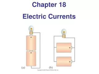
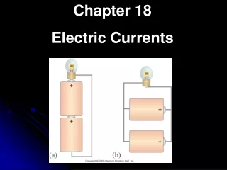
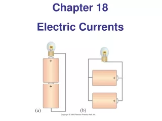
25-7 Alternating Current Current from a battery flows steadily in one direction (direct current, DC). Current from a power plant varies sinusoidally (alternating current, AC).
25-7 Alternating Current , The voltage varies sinusoidally with time: , as does the current:
25-7 Alternating Current Multiplying the current and the voltage gives the power:
25-7 Alternating Current Usually we are interested in the average power:
25-7 Alternating Current The current and voltage both have average values of zero, so we square them, take the average, then take the square root, yielding the root-mean-square (rms) value:
25-7 Alternating Current Example 25-13: Hair dryer. (a) Calculate the resistance and the peak current in a 1000-W hair dryer connected to a 120-V line. (b) What happens if it is connected to a 240-V line in Britain?
25-8 Microscopic View of Electric Current: Current Density and Drift Velocity Electrons in a conductor have large, random speeds just due to their temperature. When a potential difference is applied, the electrons also acquire an average drift velocity, which is generally considerably smaller than the thermal velocity.
25-8 Microscopic View of Electric Current: Current Density and Drift Velocity . We define the current density (current per unit area) – this is a convenient concept for relating the microscopic motions of electrons to the macroscopic current: If the current is not uniform:
25-8 Microscopic View of Electric Current: Current Density and Drift Velocity This drift speed is related to the current in the wire, and also to the number of electrons per unit volume: and
25-8 Microscopic View of Electric Current: Current Density and Drift Velocity Example 25-14: Electron speeds in a wire. A copper wire 3.2 mm in diameter carries a 5.0-A current. Determine (a) the current density in the wire, and (b) the drift velocity of the free electrons. (c) Estimate the rms speed of electrons assuming they behave like an ideal gas at 20°C. Assume that one electron per Cu atom is free to move (the others remain bound to the atom).
25-8 Microscopic View of Electric Current: Current Density and Drift Velocity The electric field inside a current-carrying wire can be found from the relationship between the current, voltage, and resistance. Writing R = ρ l/A, I = jA, andV = El , and substituting in Ohm’s law gives:
25-8 Microscopic View of Electric Current: Current Density and Drift Velocity Example 25-15: Electric field inside a wire. What is the electric field inside the wire of Example 25–14? (The current density was found to be 6.2 x 10⁵ A/m2.)
25-9 Superconductivity In general, resistivity decreases as temperature decreases. Some materials, however, have resistivity that falls abruptly to zero at a very low temperature, called the critical temperature, TC.
25-9 Superconductivity Experiments have shown that currents, once started, can flow through these materials for years without decreasing even without a potential difference. Critical temperatures are low; for many years no material was found to be superconducting above 23 K. Since 1987, new materials have been found that are superconducting below 90 K, and work on higher temperature superconductors is continuing.
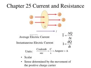
Summary of Chapter 25 • A battery is a source of constant potential difference. • Electric current is the rate of flow of electric charge. • Conventional current is in the direction that positive charge would flow. • Resistance is the ratio of voltage to current:
Summary of Chapter 25 • Ohmic materials have constant resistance, independent of voltage. • Resistance is determined by shape and material: • ρ is the resistivity.
Summary of Chapter 25 • Power in an electric circuit: • Direct current is constant. • Alternating current varies sinusoidally:
Summary of Chapter 25 • The average (rms) current and voltage: • Relation between drift speed and current:
Units of Chapter 26 • EMF and Terminal Voltage • Resistors in Series and in Parallel • Kirchhoff’s Rules • Series and Parallel EMFs; Battery Charging • Circuits Containing Resistor and Capacitor (RC Circuits) • Ammeters and Voltmeters
26-2 Resistors in Series and in Parallel A series connection has a single path from the battery, through each circuit element in turn, then back to the battery. Series = absolutely, positively, no-question-about-it same current through resistors!
26-2 Resistors in Series and in Parallel The current through each resistor is the same; the voltage depends on the resistance. The sum of the voltage drops across the resistors equals the battery voltage:
26-2 Resistors in Series and in Parallel From this we get the equivalent resistance (that single resistance that gives the same current in the circuit):
26-1 EMF and Terminal Voltage Electric circuit needs battery or generator to produce current – these are called sources of emf (archaic term: electromotive force). Battery is a nearly constant voltage source, but does have a small internal resistance, which reduces the actual voltage from the ideal emf:
26-1 EMF and Terminal Voltage This resistance behaves as though it were in series with the emf.
26-1 EMF and Terminal Voltage Example 26-1: Battery with internal resistance. A 65.0-Ω resistor is connected to the terminals of a battery whose emf is 12.0 V and whose internal resistance is 0.5 Ω. Calculate (a) the current in the circuit, (b) the terminal voltage of the battery, Vab, and (c) the power dissipated in the resistor R and in the battery’s internal resistance r.
R1 = 4 W R2 = 2 W 12 V ConcepTest 26.1b Series Resistors II 1)12 V 2)zero 3)6 V 4) 8 V 5) 4 V In the circuit below, what is the voltage across R1?
R1 = 4 W R2 = 2 W 12 V ConcepTest 26.1b Series Resistors II 1)12 V 2)zero 3)6 V 4) 8 V 5) 4 V In the circuit below, what is the voltage across R1? The voltage drop across R1 has to be twice as big as the drop across R2. This means that V1 = 8 V and V2 = 4 V. Or else you could find the current I = V/R = (12 V)/(6 W) = 2 A, and then use Ohm’s law to get voltages.
26-2 Resistors in Series and in Parallel A parallel connection splits the current; the voltage across each resistor is the same: Parallel = absolutely, positively, no-question-about-it same potential drop across resistors!
26-2 Resistors in Series and in Parallel The total current is the sum of the currents across each resistor:
26-2 Resistors in Series and in Parallel An analogy using water may be helpful in visualizing parallel circuits. The water (current) splits into two streams; each falls the same height, and the total current is the sum of the two currents. With two pipes open, the resistance to water flow is half what it is with one pipe open.
26-2 Resistors in Series and in Parallel Conceptual Example 26-2: Series or parallel? (a) The lightbulbs in the figure are identical. Which configuration produces more light? (b) Which way do you think the headlights of a car are wired? Ignore change of filament resistance R with current.
ConcepTest 26.2b Parallel Resistors II 1)increases 2)remains the same 3)decreases 4) drops to zero Points P and Q are connected to a battery of fixed voltage. As more resistors R are added to the parallel circuit, what happens to the total current in the circuit?
ConcepTest 26.2b Parallel Resistors II 1)increases 2)remains the same 3)decreases 4) drops to zero Points P and Q are connected to a battery of fixed voltage. As more resistors R are added to the parallel circuit, what happens to the total current in the circuit? As we add parallel resistors, the overall resistance of the circuit drops. Since V = IR, and V is held constant by the battery, when resistance decreases, the current must increase. Follow-up: What happens to the current through each resistor?
26-2 Resistors in Series and in Parallel Conceptual Example 26-3: An illuminating surprise. A 100-W, 120-V lightbulb and a 60-W, 120-V lightbulb are connected in two different ways as shown. In each case, which bulb glows more brightly? Ignore change of filament resistance with current (and temperature).
26-2 Resistors in Series and in Parallel Example: What is the current through each resistor shown?
26-2 Resistors in Series and in Parallel Conceptual Example 26-6: Bulb brightness in a circuit. The circuit shown has three identical lightbulbs, each of resistance R. (a) When switch S is closed, how will the brightness of bulbs A and B compare with that of bulb C? (b) What happens when switch S is opened? Use a minimum of mathematics in your answers.
26-2 Resistors in Series and Parallel Example 26-8: Analyzing a circuit. A 9.0-V battery whose internal resistance r is 0.50 Ω is connected in the circuit shown. (a) How much current is drawn from the battery? (b) What is the terminal voltage of the battery? (c) What is the current in the 6.0-Ω resistor?
Multiple configurations Assume that in each circuit the battery gives 12 V and each resistor has a resistance of 4 ohms. In which circuit does the largest current flow through the battery? What is that current?
Multiple configurations Assume that in each circuit the battery gives 12 V and each resistor has a resistance of 4 ohms. In which circuit does the largest current flow through the battery? What is that current?
Circuit Maze If each resistor has a resistance of 4 and each battery is a 4 V battery, what is the current flowing through the resistor labelled “R”?
Circuit Maze If each resistor has a resistance of 4 and each battery is a 4 V battery, what is the current flowing through the resistor labelled “R”?
26-3 Kirchhoff’s Rules Some circuits cannot be broken down into series and parallel connections. For these circuits we use Kirchhoff’s rules.
26-3 Kirchhoff’s Rules Junction rule: The sum of currents entering a junction equals the sum of the currents leaving it (i.e., charge does not pile up).
26-3 Kirchhoff’s Rules Loop rule: The sum of the changes in potential around a closed loop is zero.