Download

1 / 26
300 likes | 798 Vues
Learn about the concept of limit state in structural engineering design and how to classify sections based on their behavior under different loads. Gain insights into the IS: 800 - 1984 and IS: 800 - 2007 methods for analyzing structures and ensuring safety and serviceability.

E N D
LIMIT STATE DESIGNCLASSIFICATION OF SECTIONS Mr. Mahesh Shindepatil Assistant Professor Department of Civil Engineering.
What is Limit State? Acceptable limit for the safety and serviceability requirements before failure occurs is called a Limit state
Highlights IS : 800 - 1984 Working stress method • Factor of safely for yield stress, allowable stresses are less than ‘fy’. • Pure elastic approach for analysis of structures under working loads. • Yielding or buckling never occurs at working loads • Deformations are evaluated at working loads. IS : 800 – 2007 Limit State Method • Partial safety factor for material (γm) for yield and ultimate stress. • Working loads are factored (increased) as per partial safely factor (γf) causing Limit State of strength. • Post buckling and post yielding plays important role in estimating capacity of structural elements at Limit State. • Deformations are evaluated at working loads.
Structural elements in axial compression, bending compression tend to buckle prior yielding. To avoid this, elements of cross section such as width of flange, depth of web of I and channel section, width of legs of angle section, width of flange and leg of Tee section, width and height of Box section need to be proportioned in relation with thickness of element of section.
Classification of cross sections • A table of classification shows three distinct varieties of cross section such as plastic, compact and semi compact section. • Section in which width to thickness ratio exceeds the limits of semi compact section is known as slender section. These sections are to be avoided. • Slender section if at all used needs to ignore excess area to arrive at effective cross section as semi compact section. • If two elements of cross section fall under two different classifications then section is classified into most unfavourable classification.
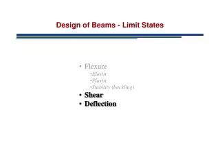
DESIGN OF BEAM COLUMN Combined action of bending and axial force (tension or compression) occurs in following situations. • Any member in a portal frame. • Beam transferring reaction load to column. • Effect of lateral load on a column due to wind, earthquake • Effect of eccentric load by crane loading due to bracket connection to column. • In case of principal rafter, purlins not placed exactly over joint of roof truss.
IS : 800 – 2007 CODAL PROVISIONS • Minimum eccentricity of load transferred by beam to column is specified by clause 7.3.3 (p. no. 46) • Section-9, Member subjected to combined forces. clause 9.3 for combined axial force and bending moment (p. no. 70) recommends check for section a) By material failure clause 9.3.1 b) By overall buckling failure clause 9.3.2
DESIGN OF BEAM COLUMN DATA A column in a building 4m in height bottom end fixed, top end hinged. reaction load due to beam is 500 kN at an eccentricity of 100 mm from major axis of section. DESIGN Column is subjected to axial compression of 5 X 10⁵ N with bending moment of 50 X 106 Nmm. Taking design compressive stress for axial loading as 80 Mpa.
Ae reqd = 500 X 103 / 80 = 6250 mm2 To account for additional stresses developed due to bending compression. Try ISHB 300 @ 0.58 kN/m Ag = 7485 sq.mm, rxx = 129.5 mm, ryy = 54.1 mm fy = 250 Mpa Classification of section b/tf = 125 / 10.6 = 11.79 > 10.5 (limit for compact section) Flange is semicompact h1/tw = 249.8 / 7.6 = 32.86 < 84 Web is plastic Therefore overall section is semicompact.
a) Section strength as governed by material failure (clause 9.3.1) Axial stress = N/Ae = 500 X 103 / 7485 = 66.80 N/mm2 Bending stress Mz/Ze = 50 X 106 / 836.3 X 103 = 59.78 N/mm2 As the section is semicompact use clause 9.3.1.3 (p. no. 71) Due to bending moment at top, horizontal shear developed ‘V’ is 18.75 kN = 18750 N Shear strength of section Vd = ((fy / √3) . h . tw) / 1.10 = 299 kN
As V/Vd = 18750 / 299 X 103 = 0.062 < 0.6 Reduction in moment capacity need not be done. As per clause 9.3.1.3 (p. no. 71) Total longitudinal compressive stress fx = 66.80 + 59.78 = 126.58 < fy/γmo = 227.27…… OK Alternately N = 500 kN Nd = Ag . fy / γmo = 7485 X 250 / 1.1 = 1701.136 kN Mz = 50 X 106 Nmm = 50 kNm Mdz = Ze . fy / γmo = 836.3 X 103 X 250 /1.10 = 190.068 kN Hence, (500 / 1701.136) + (50 / 190.068) = 0.557 < 1 ……. OK
b) Member strength as governed by buckling failure clause 9.3.2 (p. no. 71) In the absence of My, equations are reduced to Where, P = 500 X 103 N Mz = 50 X 106Nmm
Mdz = βb . Zp . fbd βb = Ze / Zp as section is semicompact Therefore Mdz = Ze fbd fbd = χLT fy / γmo χLT = bending stress reduction factor to account torsional buckling.
αLT = 0.21 for rolled section fcr,b depends on following factors kL/ ryy= 0.8 X 4000 / 54.1 = 59.15 h / tf = 300/10.6 = 28.30 Using table 14, (p. no. 57) fcr,b = 691.71 N/mm2 = 0.060 < 0.4
As per clause 8.2.2 (p. no. 54) Resistance to lateral buckling need not be checked and member may be treated as laterally supported. Mdz=Ze . fy / γmo = 190 kNm Evaluation of Pdy buckling load @ yy axis Referring table 10 (p. no. 44) h/bf=300/250 = 1.2 buckling @ yy axis is by class ‘c’ tf = 10.6 mm < 100mm buckling @ zz axis is by class ‘b’
ly / ry = 3200/54.1 = 59.15 For fy = 250 and using Table 9 (c), (p. no. 42) Fcdy = 169.275 N/mm2 Pdy = Ag. fcdy = 1267.02 kN Evaluation of Pdz buckling @ zz axis lz /rz = 3200 / 129.5 = 24.71 For fy = 250 and using Table 9 (b), (p. no. 41) fcdz = 220.76 N/mm2 Therefore pdz = Ag . fcdz = 1652.38 kN
Kz = 1 + (λz – 0.2)nz Where, lz /rz = 24.71, h/tf = 300 / 10.6 = 28.30 From table 14 (p. no. 57) fcr,z = 4040 N/mm2 Ratio of actual applied load to axial strength, nz = 500 / 1625.38 = 0.30 ny = 500 / 1267.02 = 0.39 λz = √ 250/4040 = 0.246
Kz =1 + (λz – 0.2) nz = 1.0138 < 1+0.8 nz < 1.24…. OK ψ = ratio of minimum to maximum BM ψ = -25 / 50 = -1 / 2 Cmz = 0.6 + 0.4 X (ψ) = 0.4 = 0.844
< 1 ……. OK Hence select ISHB 300 @ 0.58 kN/m as a section for eccentrically loaded column.