Limit State Method
Limit State Method. INTRODUCTION. Designer has to ensure the structures, he designs are: Fit for their purpose Safe Economical and durable. INTRODUCTION. Following Uncertainties affect the safety of a structure about loading about material strength and about structural dimensions


Limit State Method
E N D
Presentation Transcript
INTRODUCTION Designer has to ensure the structures, he designs are: • Fit for their purpose • Safe • Economical and durable
INTRODUCTION Following Uncertainties affect the safety of a structure • about loading • about material strength and • about structural dimensions • about behaviour under load
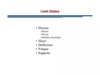
LIMIT STATE DESIGN Limit State: State at which one of the conditions pertaining to the structure has reached a limiting value Limit States Limit States of StrengthLimit States of Serviceability Strength as governed by material Deflection Buckling strength Vibration Stability against overturning, sway Fatigue cracks (reparable damage) Fatigue Fracture Corrosion Brittle Fracture Fire resistance
Frequency f(S) f(Q) Resistance, S Load effect, Q Qm Sm Probability density functions for strength and load effect RANDOM VARIATIONS
(R-Q) f(R-Q) (R-Q)m R-Q R-Q<0 R-Q>0 LIMIT STATES DESIGN • Basis of Limit States Design Fig. 1 Probability distribution of the safety margin R-Q
SAFETY INDEX Pf =[- ]
Characteristic Load Effects Characteristic Strength Factor of Safety ALLOWABLE STRESS DESIGN (ASD) • Stresses caused by the characteristic loads must be less than an “allowable stress”, which is a fraction of the yield strength • Allowable stress may be defined in terms of a “factor of safety" which represents a margin for overload and other unknown factors which could be tolerated by the structure
ALLOWABLE SRESS DESIGN (ASD) Allowable stress = (Yield stress) / (Factor of safety) Limitations • Material non-linearity • Non-linear behaviour in the postbuckled state and the property of steel to tolerate high stresses by yielding locally and redistributing the loads not accounted for. • No allowance for redistribution of loads in statically indeterminate members
LIMIT STATES DESIGN • “Limit States" are various conditions in which a structure would be considered to have failed to fulfil the purpose for which it was built. • “Ultimate Limit States” are those catastrophic states,which require a larger reliability in order to reduce the probability of its occurrence to a very low level. • “Serviceability Limit State" refers to the limits on acceptable performance of the structure during service.
General Principles of Limit States Design • Structure to be designed for the Limit States at which they would become unfit for their intended purpose by choosing, appropriate partial safety factors, based on probabilistic methods. • Two partial safety factors, one applied to loading (f) and another to the material strength (m)shall be employed.
fallows for; • Possible deviation of the actual behaviour of the structure from the analysis model • Deviation of loads from specified values and • Reduced probability that the various loads acting together will simultaneously reach the characteristic value.
(Resistance ) (Resistance Factor) (Load * Load Factor) LIMIT STATES DESIGN • m takes account; • Possible deviation of the material in the structure from that assumed in design • Possible reduction in the strength of the material from its characteristic value • Manufacturing tolerances. • Mode of failure (ductile or brittle)
IS800 SECTION 5 LIMIT STATE DESIGN • 5.1 Basis for Design • 5.2 Limit State Design • 5.3 Actions • 5.4 Strength • 5.5 Factors Governing the Ultimate Strength • 5.5.1 Stability • 5.5.2 Fatigue • 5.5.3 Plastic Collapse • 5.6 Limit State of Serviceability • 5.6.1 Deflection • 5.6.2 Vibration • 5.6.3 Durability • 5.6.4 Fire Resistance
5.1 Basis for Design • the structure shall be designed to withstand safely all loads likely to act on it throughout its life. • It shall also satisfy the serviceability requirements, such as limitations of deflection and vibration. • It shall not suffer total collapse under accidental loads such as from explosions or impact or due to consequences of human error to an extent beyond the local damages. • The objective of design is to achieve a structure that will remain fit for use during its life with an acceptable target reliability.
5.1.3 The potential for catastrophic damage shall be limited or avoided by appropriate choice of one or more of the following: • i) avoiding, eliminating or reducing exposure to hazards, which the structure is likely to sustain. • ii) choosing structural forms, layouts and details and designing such that • the structure has low sensitivity to hazardous conditions. • the structure survives with only local damage even after serious damage to any one individual element by the hazard.
Conditions to be satisfied to avoid a disproportionate collapse • building should be effectively tied together at each principal floor level and each column should be effectively held in position by means of continuous ties (beams) nearly orthogonal • each storey of the building should be checked to ensure disproportionate collapse would not precipitate by the notional removal, one at a time, of each column. • check should be made at each storey by removing one lateral support system at a time to ensure disproportionate collapse would not occur.
Actions • 5.3.1 Classification of Actions • by their variation with time as given below: • a) Permanent Actions (Qp): Actions due to self-weight of structural and non-structural components, fittings, ancillaries, and fixed equipment etc. • b) Variable Actions (Qv): Actions due to construction and service stage loads such as imposed (live) loads (crane loads, snow loads etc.), wind loads, and earthquake loads etc. • c) Accidental Actions (Qa): Actionsdue to explosions, impact of vehicles, and fires etc.
5.5 Factors Governing the Ultimate Strength • frame stability against overturning and sway • Fatigue design shall be as per Section 13 of this code. When designing for fatigue, the load factor for action,f, equal to unity shall be used for the load causing stress fluctuation and stress range. • Plastic Collapse Plastic analysis and design may be used if the requirement specified under the plastic method of analysis (Section 4.5) are satisfied.
5.6 Limit State of Serviceability • Deflectionsare to be checked for the most adverse but realistic combination of service loads and their arrangement, by elastic analysis, using a load factor of 1.0 • Suitable provisions in the design shall be made for the dynamic effects of live loads, impact loads andvibration/fatiguedue to machinery operating loads. • The durabilityof steel structures shall be ensured by following recommendations of Section 15. • Design provisions to resistfireare briefly discussed in Section 16.