Poolside Alarm
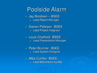
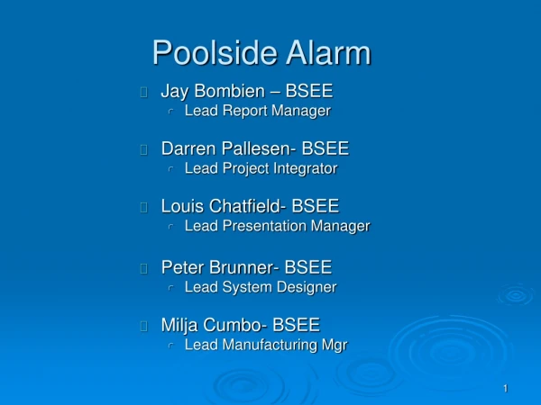
Poolside Alarm. Jay Bombien – BSEE Lead Report Manager Darren Pallesen- BSEE Lead Project Integrator Louis Chatfield- BSEE Lead Presentation Manager Peter Brunner- BSEE Lead System Designer Milja Cumbo- BSEE Lead Manufacturing Mgr. Major Functions and Features. Functions:

Poolside Alarm
E N D
Presentation Transcript
Poolside Alarm • Jay Bombien – BSEE • Lead Report Manager • Darren Pallesen- BSEE • Lead Project Integrator • Louis Chatfield- BSEE • Lead Presentation Manager • Peter Brunner- BSEE • Lead System Designer • Milja Cumbo- BSEE • Lead Manufacturing Mgr
Major Functions and Features • Functions: • Monitor a pool for potential hazardous situations • Loud audible alarm when a child falls in unnoticeably • Features: • Outdoor unit will display water temperature • Solar cells on poolside unit to keep outdoor battery charged • Wireless home receiver and display unit with loud audible signal. • User Control On/Off and Alarm Active/Deactive
Poolside Alarm Block Assignment Louis Peter Jay Darren Milja Outdoor Indoor Power Supply Power Supply Water Temp Sensor Alarm RF Transceiver Wave Sensor Indoor MPU and Display Motion Sensor Data Lines Power Lines Alarm
Performance Requirements Operational Modes On, Off Alarm Active / De-active Effectiveness • False Alarms < 5% • Alarm Duration 5 Minutes Digital Signal Interface Requirements • Vih (min) = 2.0 v Vil (max) = 0.8 v Voh (min) = 2.4 v • Iih (max) = 5 uA Iil (max) = -5 uA Ioh (max) = -3.2 mA • VoL (max) = 0.5 v IoL (max) = 24 mA RF transmission Range: 300ft
Performance Requirements Mechanical Interfaces • Water Temp Sensor • Motion Sensor • Wave Sensor • LED Display – Indoor Unit • 7-segment Display – Outdoor Unit • Antenna for RF Transceiver User Interface Types • Product On/Off switch • Alarm On/Off switch • 7-segment water temp LED display – Outdoor unit • LED indicators – Indoor Unit User Interface details • User can turn off alarm at discretion by means of a switch
Performance Requirements Power Input Types Indoor: • Source(1): 120Vac 108V to 138V Frequency Range: 57-63Hz Connectors: 1) Type B (Flat blades with round grounding pin) 2) 2.1 mm male-to-female DC Plug • Source(2): Lithium 9V 7.5 – 9.9V • Battery Capacity: 1200 mAh Outdoor: • Source(1): Solar Cell 0V to 16.5V • Source(2): 3 x Li+ 9.9V to 12.6V • Battery Capacity 2000 mAh • Connector (IP67) 2-pin Micro-Con-X subminiature
Performance Requirements User Interface Details Outdoor: 3-digit, 7-segment display • Color: Red • Visibility: 5m (day), 10m (night) • Numeric Characters (0-9) • Size: 0.4” Indoor: LED indicators • Red and Green LEDs • Display power, low battery, outdoor unit off, and alarm activated • Visibility: 10m (day) • 24 Font Size Labels Labeling • Indoor On/Off switch • Outdoor On/Off switch • Warning labels for shock hazard: Indoor AC adapter, outdoor solar panel • Temperature display ºF
Standard Requirements Market: • Est. Total Market Size $1,000,000 • Est. Annual Vol. 2,000 • Min. List Price $300 • Target United States • Demographic Parents with pools Manufacturing: • Min. Total Parts Count 200 • Max. Unique Parts Count 100 • Max. Parts & Materials Cost $175 • Max. MFG Assembly / Test Cost $50
Standard Requirements Life Cycle: • Est. Max. Production Lifetime 5 years • Product Life Reliability in MTBF 4 years • Full Warranty Period 30 days • Reliability (warranty) 95% • Disposal Throw Away Application and Limitations • Pool size Round, up to 24’ diameter • Battery Type (outdoor) Lithium Ion (3.7V nominal) • Weight of child (min) 18lbs • Loudness of alarm 100dB at 10ft
Standard Requirements Mechanical: • Max. Product Vol. 5,000 cm3 • Max. Shipping Container Vol. 7,000 cm3 • Max. Product Mass 13 kg • Max. # of boards 3 • Max. Total PCB Area 425 cm2 • Max. Shock Force • Indoor 50 G’s • Outdoor 10 G’s • Max. Shock Repetitions / Year 15 Environmental: • Operating temperature range 5 to 55 C • Operating humidity 0 to 100% • Operating Pressure Range -500m to 5000m • Storage temperature range -20C to 65C • Storage Ambient Humidity Range 0%RH to 100%RH • Storage / Shipping Altitude Range -1000m to 5000m
Safety Standards • UL 464 - Audible Signal Appliances • Electrically and electronically operated bells, buzzers, horns, and similar audible signal appliances intended for indoor or outdoor locations. • UL 1703 - Flat-Plate Photovoltaic Modules and Panels • Flat-plate photovoltaic modules used as either freestanding or attached to buildings • PS 128-01, Provisional Specification for Pool Alarms • Alarms sound at poolside and in adjacent buildings when a minimum weight of 18 lbs hits the water. • PS 128-01, Provisional Specification for Pool Alarms • Alarms sound at poolside and in adjacent buildings that a minimum sound of 80dB at 100ft is possible • IEC 61558-1 • Safety of power transformers, power supply units and similar devices
Outdoor Power Supply Peter Brunner
Poolside Alarm Block Assignment Peter Outdoor Indoor Power Supply Power Supply Alarm Water Sensor RF Transceiver Wave Sensor Indoor MPU and Display Motion Sensor Data Lines Power Lines Alarm
Outdoor Power SupplyBlock Description • To receive Infra red rays from the sun to charge the solar panels • To recharge the batteries through a regulator when it is 9.9V or lower. • To output the required regulated voltage for the other block power inputs
Outdoor Power SupplyPerformance requirements Electrical Interfaces: • Signal Type: Power - DC • Power Input: 19.8Wmax • Source1: Battery • Type: 3 X Lithium Ion • VBAT, MIN = 3.3V • Capacity = 2000mAH • Max. Charging current: 2.4A • Max. Discharging current 3A • Source2: 30 X Solar Cells • Voltage (30X cells): Nominal: 16.5 Range: 0 – 16.8 • Current max:1A • Output Voltage: • Nominal: 3.3 Range: 3-3.6 • Nominal: 9 Range: 8.1-9.9 • VRIPPLE = 100mV • Output Current max: 2 * 0.5A = 1A
Outdoor Power SupplyPerformance requirements Mechanical interfaces • Connector: Solar Panel to Unit • IP67 rated: 2-pin Micro-Con-X subminiature • Power on/off toggle switch Operational Modes • On, Slow charge, Fast charge
Mechanical Block cost <$34 Cost Allocation 15% Parts count <45 Part Allocation 23% Unique parts count <25 PCB Area 40 cm2 PCB allocation 9% Environment: Operating temperature range 5 to 55 C Operating humidity 0 to 100% Operating Pressure Range -1000m to 5000m Storage temperature range -20C to 65C Storage Ambient Humidity Range 0%RH to 100%RH Storage / Shipping Altitude Range -1500m to 5000m Outdoor Power SupplyStandard requirements
Outdoor Power SupplyStandard requirements Life Cycle • Reliability MTBF 5 years • Reliability % 45% • R (warranty) 95% • Disposal Throw away
Outdoor Power SupplyStandards • Safety Feature Requirements • Waterproof (IP67) Connector/cap to avoid water on input pins. • Components possess high voltage and current ratings so overheating does not occur • Completely enclosed supply reduces shock potential and chance for water shorting • Heat sink for VSOLAR input. • Safety Standard: • UL 1703 - Flat-Plate Photovoltaic Modules and Panels • EMC Standard: • EMC 61000-3-3: Limitation of voltage fluctuations and flicker in low-voltage supplies <16A
Outdoor Power SupplyBlock Assignment Sun VPower VCharge Solar Panel Charging Circuit Switching Regulator Battery V3.3V V9V Other Blocks
Outdoor Power SupplyCalculations VOUT = 9V
Outdoor Power SupplyCalculations VOUT = 3.3V
Outdoor Power SupplyComponent Selection • Solar Panel is 18AWG • Handle more than 1A current at 16.5V • All other wires are 22AWG • Can easily handle circuitry current • RS2 & RS1 are 1/2W • Both resistors can handle current required • Conxall IP67 connector – 7A max contact • Easily handle max 1.2A • Weatherproof connection • Max5035 • Large input voltage range • 1A output current • Highly efficient regulated output • Max1909 • Up to 7A input current • Up to 4A charge current • Automatically switches from Battery to DC power
Outdoor Power SupplyWorst-Case DFM analysis • Input voltage range (min) 9V & 3.3V: • VBATT,MIN = 9.9V • VIN,MIN = 9.6V • VBATT,MIN ≥ VIN,MIN • As long as VBATT,MIN > 9.6V, Chip will remain on, output will be 9V or 3.3V, respectively • Input voltage range (max) • VBATT,MAX = 12.6V, VSOLAR, MAX = 16.5V • VCHIP,MAX = 76V • VBATT,MAX < VCHIP,MAX • VSOLAR, MAX < VCHIP,MAX • Neither solar or battery voltage will exceed max input voltage
Outdoor Power SupplyWorst-Case DFM analysis • Battery life • Max mAH • Momentarily ON • Alarm on for 5 minutes = 31.667mA • Water Temp = 1 minute/day = 3.65mA • Continuously ON • Motion Sensor = 25mA • Wave Sensor = 17mA • RF transceiver = 43mA
Outdoor Power SupplyWorst-Case DFM analysis • Battery Charging Continued • 1 hour max mA • 25 + 17 + 42 + 219/60 + 380/12 = 120.3 • 1 hour avg mA • 25+17+43 = 85 • Worst-Case average mA = (23*85 + 120.3) / 24 = 86.472 • Worst-Case Battery Life = (2000mA*H /86.743) = 23Hrs
Outdoor Power SupplyWorst-Case DFM analysis • VOUT = 3.3V and VUVLO, Shutdown = 5.2V • VOUT = 9V with VUVLO, Shutdown = 9.9V • Meet min requirement • of Vout = +/- 10%
Outdoor Power SupplyWorst-Case DFM analysis Battery Charger
Bill Of Materials Total Parts: 84 Total Cost: $116.34 * Total Parts and Total Cost exceed standard requirement. Can reduce major cost by using lower quality solar cells
Outdoor Power SupplyManufacturing Process Manufacturing: 1) X-ray solder joints of SMT components. Inspection of defects such as gull wings, J-Lead defects, or discrete chip resistors 2) Manual placement of specified components • - Machine Placement: • SMD passives • SMD IC’s • Manual Placement: • Batteryclip • Bulkhead connector / cap • Solar Panel • Toggle switch • Pushbutton switch • Machine Solder: • SMD passives • SMD IC’s • Manual Solder: • Socket connector to Solar panel • Lead wires to PCB • 30 X solar cells
Outdoor Power SupplyTest Processes Test 1: - Action: Place solar panel under bright light - Verify: Proper open-circuit voltage and short-circuit current Test 2: - Action: Apply different loads to the 9V and 3.3V output - Verify: Max required current, acceptable nominal voltage outputs Test 3: - Action: Connect solar panel to enclosure. Then remove it - Verify: Proper switching between Solar panel and battery source Test 4: - Action: Mechanical vibration. Use machine to gently shake the circuit board. This test will NOT include the Solar Panel - Verify: Parts do not fall off
Parts Count Reliability • Total Fits = 13618, Total MTBF (yrs) = 8.377 • Reliability (1 warranty) = 97.1% • The required reliability (MTBF) goal is 5 years and reliability after 1 warranty is 97.1%. This block exceeds the requirements • - Dominant Failure part is the Solar Panel. Not much can be done to improve this part for higher reliability.
Outdoor Power SupplySustainability Life Cycle: 5 years Major Problem Part: The Quad Flat Pack (Li+ battery charge controller) will be obsolete in March, 2013. But since our life cycle is only 5 years, this part will not be a problem for this product. Near obsolete parts: The thick film resistors, inductors, ceramic capacitors, SOP package and the Quad Flat Pack are the most dangerous parts to use since they will be phasing out near the end of our product life. However, they will not be completely obsolete by the end of the product life so there is not a need to change them.
RF Transceiver Milja Cumbo
Poolside Alarm Block Assignment Milja Outdoor Indoor Power Supply Power Supply Alarm Air / Water Sensor RF Transceiver Wave Sensor Indoor MPU and Display Motion Sensor Data Lines Power Lines Alarm
RF Transceiver Block Purpose and Description Processing and controlling data from sensors, power supplies, and switches Transmitting and receiving data between outdoor and indoor units
Product PerformanceRequirements I/O Interface Mechanical interfaces Vih(min)=2.0[V] Sensors, Indoor MPU Vil(max)=0.8[V] Iih(max)=5[uA] Voltage Range Iil(min)=-5[uA] 2.1 V – 3.6 V Vol(max)=0.5[V] Ioh(min)=-24[mA] Supply Current Iol(max)=24[mA] 30 mA Effectiveness I/O pins >15 speed 10 ns Different Signal Directions I/O/Bi-Dir Operational Mode Power/Alarm: On/Off
RF TransceiverProduct Standard Requirements Block cost <$50 10%(tot.) Parts count <60 25%(tot.) Unique parts count <5 5 %(tot.) PCB Area 50 cm2 15%(tot.) Power consumption <2W Operating temperature range 5 0C to 55 0C Storage temperature range -20 0C to 65 0C Operating humidity 0-100% RH Life Cycle MTBF 50 years R(t) % 90 % R (%) Allocation 10 % Disposal Throw Away
US/FCC:47 CFR 15 - Radio Frequency Devices 47 CFR 18 - Industrial Scientific and Medical Equipment 61000-3-3 EMC Part 3: Limits - Section 3: Limitation of voltage fluctuations and flicker in low-voltage supplies <16A 61000-4-2 EMC Part 4: Test/measurement techniques - Section 2: ESD immunity tests 61000-4-3 EMC Part 4: Test/measurement techniques - Section 3: Radiated radiofrequency immunity tests 61000-4-6 EMC Part 4: Test/measurement techniques - Section 6: Conducted Radiofrequency immunity tests CISPR:11 Limits and methods of measurement for Industrial, Scientific and Medical Equipment 16 Specifications for Radio Interference Measuring Apparatus and Measurement Methods 22 Limits and Methods of Measurements of Radio Interference of Information Technology Equipment EMC Standards Summary
RF Transceiver Block Diagram digital signals CLK digital signals Alarm Status Low Battery Power Status Alarm Deactivated From Inside Water Sensor Motion Sensor Outside Controller Power Low Battery PushButton Outdoor Transceiver Indoor Transceiver ¼ whip antenna (outdoor) ¼ whip antenna (indoor) Crystal Crystal
RF Transceiver Detailed Design Calculations The fundamental link to deliver sufficient power from the transmitter to the receiver. Free space path loss can be calculated from the following formula Lp(dB) = 32.4 + 20log(f[MHz]) + 20log(d[km]), from there we can substitute Lp into the equation to calculate expected signal power at the receiver: Lr = Ptx – Lp. MAX7031 Transceiver specifications are: Frequency is 433.92 MHz Typical output power of 10 dBm into a 50 Ohm load, and typical sensitivity of -108 dBm Transmitting distance is 300 ft (91.44 m or 0.9144 km). After substituting, we find that the expected signal power at the receiver is -74.37 dBm which satisfies the specifications of the receiver sensitivity (-108 dBm)