Input/Output Modules A Brief Overview
Input/Output Modules A Brief Overview. Overview. Basic Input/Output (I/O) Module Some Features Slew Rate Control Different I/O Standards Input Delays Banks Deterministic Powerup Cold Sparing Transition Times Input and Output. Act 1.

Input/Output Modules A Brief Overview
E N D
Presentation Transcript
Overview • Basic Input/Output (I/O) Module • Some Features • Slew Rate Control • Different I/O Standards • Input Delays • Banks • Deterministic Powerup • Cold Sparing • Transition Times • Input and Output
Act 1 • Many families have slew rate control to limit signal reflections and ground bounce. • Different families drive their outputs to different levels.
Act 2 tSU = 0 tH > 0 Can combine with latches in the array to make flip-flops
Act 3 I/O - Logic tH = 0 I/O clock is distinct from the array clocks, both routed and dedicated.
I/O Features Description Function Input buffer • 4 level selections - LVTTL, 3.3V PCI, 5V CMOS, 5V PCI/TTL • Selectable on an individual I/O basis • 5 volt tolerant • “Hot-swap” capability • Unpowered dev. I/O doesn’t sink current • Can be used for “cold-sparing” • Selectable on an individual I/O basis • Individually selectable low-slew option • Indiv. selectable current lamp preventing reflections of a signal > 3.3 volts (VCCI) • Indiv. selectable pull-ups/downs during power-up (default to power-up in tri-state) • Enables deterministic power-up of device • Pull-ups/downs are disabled 50ns after VCCA (array) is powered up and functioning • VCCA & VCCI can be powered in any order Output buffer 3.3 Volt PCI Power-up
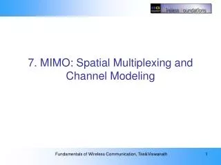
RTSX-S Input Levels Input levels independently selectable on an I/O by I/O basis. VCCI=5.0V VCCI=3.3V Vih(min) Vil(max) • Trip points referenced to VCCI which controls the output drive level. • 5.0V CMOS selection designed exclusively for RTSXS to maximize noise immunity in a 5 volt CMOS system.
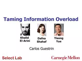
Cold Sparing - SX-S • “Hot-Swap” selectable on an individual I/O basis. • Spare boards can be powered off until needed. • Low TID component boards can be powered off in order to extend mission lifetime. Powered-up Board 3.3/5 Volts Powered-down Board VCCI RTSX-S 0 Volts GND Active Bus or Backplane VCCI RTSX-S GND I/O w/ ” Hot-Swap” Enabled does not sink current
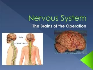
Deterministic Power-up - SX-S (outputs can be set to power-up either high or low) VCCA VCCI • Pull-ups /downs are selectable on an individual I/O basis • Pull-up follows VCCI • Pull-downs and pull-ups are dis- abled 50 ns after VCCA reaches 2.5V and therefore do not draw current during regular operation. • Once VCCA is powered-up, 50ns is required for a valid signal to propagate to the outputs before the pull-ups /downs are disabled RTSX-S Pull-up enabled PRE Input Driven low or external POR Signal CLR Pull-down enabled
Virtex 2.5V- I/O Banking VCCO Compatible Standards 3.3V PCI, LVTTL, SSTL3 I, SSTL3 II, CTT, AGP, GTL, GTL+ 2.5V SSTL2 I, SSTL2 II, LVCMOS2, GTL, GTL+ 1.5V HSTL I, HSTL III, HSTL IV, GTL, GTL+
Virtex 2.5V I/O Standard Input Ref Output Board 5V Voltage Source Termination Tolerant (VREF) Voltage Voltage (VCCO) (VTT) LVTTL 2–24 mA N/A 3.3 N/A Yes LVCMOS2 N/A 2.5 N/A Yes PCI, 5 V N/A 3.3 N/A Yes PCI, 3.3 V N/A 3.3 N/A No GTL 0.8 N/A 1.2 No GTL+ 1.0 N/A 1.5 No HSTL Class I 0.75 1.5 0.75 No HSTL Class III 0.9 1.5 1.5 No HSTL Class IV 0.9 1.5 1.5 No SSTL3 Class I &II 1.5 3.3 1.5 No SSTL2 Class I & II 1.25 2.5 1.25 No CTT 1.5 3.3 1.5 No AGP 1.32 3.3 N/A No
AT60xx I/O Module (3) Enable Select User-configurable bits determine the output-enable for the output driver. The output driver can be static – always on or always off – or dynamically controlled by a signal gener-ated in the array. Four options are available from the array: (1) the control is low and always driving; (2) the control is high and never driving; (3) the control is connected to a ver-tical local bus associated with the output cell; or (4) the control is connected to a horizontal local bus associated with the output cell. On power-up, the user I/Os are config-ured as inputs with pull-up resistors. In addition to the functionality provided by the I/O logic, the entrance and exit cells provide the ability to register both inputs and outputs. Also, these perimeter cells (unlike inte-rior cells) are connected directly to express buses: the edge-facing A and B outputs of the entrance cell are con-nected to express buses, as are the edge-facing A and B inputs of the exit cell. These buses are perpendicular to the edge, and provide a rapid means of bringing I/O signals to and from the array interior and the opposite edge of the chip. TTL/CMOS Inputs A user-configurable bit determines the threshold level – TTL or CMOS – of the input buffer. Open Collector/Tristate Outputs A user-configurable bit which enables or disables the active pull-up of the output device. TTL/CMOS Inputs A user-configurable bit determines the threshold level – TTL or CMOS – of the input buffer. Open Collector/Tristate Outputs A user-configurable bit which enables or disables the active pull-up of the output device. PC parallel port, microprocessor, EPROM or serial configu-ration memory can be used to download configuration patterns. Users select from several configuration modes. Many fac-tors, including board area, configuration speed and the number of designs implemented in parallel can influence the user’s final choice.