AccuMax Single Point Injection
280 likes | 439 Vues
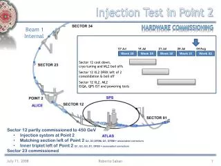
AccuMax Single Point Injection Operation (See Installation and Operation Manual for detailed instructions). AccuMax Single Point Injection. Digital Display Control. Foam Tank. Line Strainer. Water Tank. Check Valves. Flowmeter. Multiple Discharges. Water Pump.

AccuMax Single Point Injection
E N D
Presentation Transcript
AccuMaxSingle Point InjectionOperation(See Installation and Operation Manual for detailed instructions)
AccuMax Single Point Injection Digital Display Control Foam Tank Line Strainer Water Tank Check Valves Flowmeter Multiple Discharges Water Pump
Digital Display Operation • Digital display reads “Hypro” upon initial power-up • System then enters flow mode in standby • Operates as flowmeter
Digital Display Operation • Push red “FOAM” button to arm system • “ON” light illuminates • Open foam discharge • Displays solution volume • “ON” light blinks when foam pump runs
Digital Display Operation • Water flow display • Push “SELECT” button and total volume of water discharged is displayed • Gallons, liters, imperial gallons
Digital Display Operation • Push “SELECT” button to enter “%” mode • Displays default injection percentage • “PA” Single tank system • “PC” Remote start/stop (“UP” or “DOWN” button will override default setting)
Digital Display Operation • Push “SELECT” button to enter “TOTAL FOAM” • Displays total concentrate injected • Dual-tank mode • Totals for each tank • Display corresponds to tank chosen by dual-tank valve
Digital Display Operation • Enter “INJECTION PERCENTAGE” from any mode • Press either “UP” or “DOWN” button momentarily to display current percentage setting • Hold either button for two seconds to change setting accordingly
Operating Instructions System Reset Total Water%(Percent)Total Foam • Reset these modes to 0 or % to default setting • Push both the up and down buttons in desired mode
Flowmeter Size Max Accuracy Max Operating Tee Flow RangeFlow Range 1-1/2x1" 5 - 110 gpm 3 - 145 gpm 1-1/2" 10 - 320 gpm 3 - 380 gpm 2" 15 - 520 gpm 5 - 625 gpm 2-1/2" 20 - 750 gpm 8 - 900 gpm 3" 30 - 1150 gpm 12 -1380 gpm 4" 55 - 1980 gpm 20 - 2380 gpm 6" ** 70 - 2800 gpm 30 - 3300 gpm 8" ** 120 - 4800gpm50 - 5600 gpm ** Electromagnetic flowmeter No Flow Restrictions
Low Foam Display • When Lo con is Displayed • Selected foam concentrate tank is getting low • If foam concentrate is added within 2 minutes Lo con goes out • If no foam concentrate is added within 2 minutes no con is displayed • When no con is Displayed • Foam concentrate pump will not run • Add foam concentrate until no con display goes out then push Red Foam button to start the foam pump
Exceeding Foam Injection Rate • Hi Flo display • Occurs when the water flow and selected foam concentrate injection percentage exceeds the foam pump capabilities • Informs pump operator when this situation occurs • Lower the foam concentrate injection percentage or water flow to stop the flashing Hi Flo display
Motor Driver • Module controls pump motor • Totally enclosed environmentally sealed • Incorporates system circuit breaker
Digital Display Operation • Simulated flow • While in “FLOW” mode, push both lower buttons simultaneously • Three bars on left indicate manual mode • Pushing red “FOAM” button will turn foam pump on/off • Pump injects to simulated flow default setting
System Air Purge • Enter “SIMULATED FLOW” • Turn injection valve from “INJECT” to “CAL/FLUSH” • Push red “FOAM” button on display to start foam pump
System Air Purge (cont.) • Run until concentrate flows steady out of dump line • Push red “FOAM” button to stop pump • Turn injection valve to “INJECT” • Exit “SIMULATED FLOW”
AccuMaxSingle Point Foam Pump • Hydraulic pump • Housing incorporates speed sensor • Positive displacement plunger pump • Components made of corrosion resistant materials • Max operating pressure is 400 psi
System Maintenance • Clean strainer(s) regularly • Purge pump to remove air pockets afterwards • Check oil level • Dip stick reading or • Sight glass
Concentrate Management Systems (Only Available on AccuMax Single Point Models 3020 and 3040)
Foam Tank B Foam Tank A Manual CMS
Foam Tank B Foam Tank A Electronic CMS
Digital Display Operation • Dual-tank function • Dual-tank valve in “A” • Displays “PA” and default setting • Dual-tank valve in “B” • Displays “Pb” and default setting • Default settings from 0.1 to 6.0%
Dual-Tank Flush • Flush after using Class B foam • Flow water and engage foam system • Turn manual valve to “FLUSH” or electric valve to “OFF” (“Off” position is a constant flush)
Flowmeter Flowmeter Flowmeter Flowmeter MultiFlo Interface MultiFlo Display Control Cable Flowmeter Cable Std. Controller or AFC