AccuMax Foam Injection System | Efficient foam solution control for industrial settings
720 likes | 758 Vues
The AccuMax Foam Injection System offers precise foam solution control with features like Multi-Point Injection, Electronic Direct Injection, and Internal Controls. Complete with Hydraulic Motor Control and a 12-digit display.

AccuMax Foam Injection System | Efficient foam solution control for industrial settings
E N D
Presentation Transcript
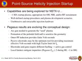
Internal Controls Line Drivers Power Terminals Foam Pump Line Controls Master Flowmeter Foam Inlet from Tank Foam Manifold Hydraulic Motor
Control Head 12 digit display Display select button 6 digit display Lighted On/Off Button Configuration internal switch Calibrate internal switch Reset and up/down adjust pushbuttons
Initial Power Up Display Line Master • Operate the apparatus engine and engage PTO to Hydraulic pump • Turn on electrical power to the FoamPro system • After a system check the Control Displays will read as shown above
Make Foam Solution Line Master • Establish water flow to the foam capable discharge • The Line Control Display will indicate the water flow rate • Press the green I/O button on the Master Control Display • Press the green I/O button on the Line Control Display • The foam pump will start to deliver foam at the rate preset by the operator • The Master Control Display will indicate the foam injection pressure and the total water flow of all foam capable lines
Total Water Flowed Line Master • To read the total water used on a line, press the SELECT button on the Line Control Display until the display reads as above. • To read the total water used on all foam capable lines, press the SELECT button on the Master Control Display until the display reads as above. • To reset the value on either display, press both the UP and DOWN buttons at the same time.
Reading % Injection Rate • Press the SELECT button on the Line Control Display until the display reads the current rate. • To change the rate press the UP or DOWN button on the Line Control Display on the line you wish to change. • Pressing the UP or DOWN button will toggle between the preset values of Preset 1, Preset 2, Preset 3, and Custom rate.
Changing Custom Injection Rate • Holding the UP or DOWN button will change the rate in 0.1% increments until the button is released. This new value will become the new custom rate until changed.
Read Total Chemical Used Line Master • To read the total chemical used on whole the system, press the SELECT button on the Master Control Display until the display reads as shown. • To read the total chemical used on any specific line, press the SELECT button on the Line Control Display of the selected line until the display reads as shown. • To reset the value on either the Master Or Line Control Display, press both the UP and DOWN buttons at the same time.
Read Water Flow Rate Line Master • To read the total water flow rate of the foam system, press the SELECT button on the Master Control Display until the display reads as shown. • To read the total water flow rate of a specific foam discharge, press the SELECT button on the appropriate Line Control Display until the display reads as shown.
Read Foam Injection Pressure Master Line Or To read total water flow rate and injection pressure, press the SELECT button until the display reads as shown on the right. The top number will show the injection pressure and the larger bottom number will show the total flow rate. Or Press the Select button until the display reads as shown on the left for injection pressure only.
Simulated Water Flow Operation The simulated flow function of the system allows the operator to control the line injection and foam pump manually. The water flow rate and the concentrate injection percentage rate can be set by using the display readout and the rate adjustment buttons on the Line Control Display Module. • This function provides the manual control requirement of NFPA. • This function will allow the operator to empty or fill the foam concentrate tank for cleaning, changing foam types, or refilling . • This function also provides a means of checking the operation of the foam pump at all normal rates of flow and injection without running the water pump. WARNING: When operating in the simulated mode, an outlet for the foam concentrate must be provided.
Initiate Simulated Flow Operation Line Master • Press the SELECT button until the display reads as shown on the left. • Press the UP/DOWN buttons simultaneously. The display will read as shown on the right. • Start the system by pressing the I/O button on both the Master Control Display and the Line Control Display.
Changing Simulated Flow Rate Press the UP button to increase the flow rate or the DOWN button to decrease the flow rate. The rate will change in increments of 100.
Exit Simulated Flow Operation Line Master • Press the SELECT button until the display reads as shown on the left. • Press the UP/DOWN buttons simultaneously and the display will read as shown on the right. • The Line Control is now in the normal operating mode.
Configuration Operation The FoamPro AccuMax system permits easy configuration setup of the system Display Controllers for proper operation. This process needs to be done at time of installation , or when a display is replaced. To enter the Configuration Mode, remove the left hand cover screw and o-ring with a 3/32” Allen wrench, located between the I/O and the UP button. Using the Allen wrench, depress the internal switch once. To exit the Configuration Mode, use the Allen wrench to depress the internal button once, and the Display will return to the normal operating mode. Be sure to replace both the o-ring and the screw after exiting the mode. The following slide will show the location of the Configuration switch.
Control Head 12 digit display Display select button 6 digit display Lighted On/Off Button Configuration internal switch Calibrate internal switch Reset and up/down adjust pushbuttons
Master Configuration Entering the Configuration Mode of the Master Display Module will cause the display to read as shown above.
Master Configuration Pressing the SELECT button once will show the display shown above. This is the group number for the bus system and will remain at 0.
Master Configuration • Pressing the SELECT button once will show the display on the left. • This is the sets the AUTO-START feature that will allow the system to start operations in the ON mode when powered up. • NO is the default setting and disables the feature. • Yes, enables the feature and requires the pressing of the DOWN button once. The display will read as shown on the right.
Master Configuration • Pressing the SELECT button once will configure the temperature feature that will display the temperature of the circuit boards. • The default is set to read this temperature in °F. • Press the DOWN button once changes this to °C.
Master Configuration • Pressing the SELECT button once will place the configuration mode to the usage of a pressure transducer. • The default from the factory is set for unused as shown on the left. • Pressing the DOWN button once will enable this feature and will set the units to PSI, as shown in the center display. • Pressing the DOWN button once more will change the units to BAR as shown on the right display. • Note: The Master Control Module requires the pressure feature to be used and PSI or BAR must be selected.
Line Configuration Entering the Configuration Mode of the Line Display Module will cause the display to read as shown above.
Line Configuration Pressing the SELECT button once will show the display as shown. This identifies the discharge number assigned by the Master upon system startup. To change the number, press the UP or Down button accordingly.
Line Configuration Pressing the SELECT button once will show the display shown above. This is the group number for the bus system and will remain at 0.
Line Configuration • Pressing the SELECT button once will show the display on the left. • This is the sets the AUTO-START feature that will allow the system to start operations in the ON mode when powered up. • NO is the default setting and disables the feature. • Yes, enables the feature and requires the pressing of the DOWN button once. The display will read as shown on the right.
Line Configuration • Pressing the SELECT button once will configure the temperature feature that will display the temperature of the circuit boards. • The default is set to read this temperature in °F. • Press the DOWN button once changes this to °C.
Line Configuration • Pressing the SELECT button once will place the configuration mode to the usage of a pressure transducer. • The default from the factory is set for unused as shown on the left. • Pressing the DOWN button once will enable this feature and will set the units to PSI, as shown in the center display. • Pressing the DOWN button once more will change the units to BAR as shown on the right display. • Note: The Master Control Module requires the pressure feature to be used and PSI or BAR must be selected.
Master Setup & Calibration The Master Control Module needs to be setup and calibrated to run the system. To enter this mode, depress the right internal switch once. The display will read as shown.
Master Foam Flowmeter Calibration Depress the SELECT button until the display reads as shown. Since any one of the lines needs to be open to run the Foam Pump, pick one of the lines to calibrate with the Master at this time. Enter the Setup Calibration Mode of the chosen Line Control Display by depressing the right internal switch once. The Line Control Display will read as shown above.
Master Setup & Calibration Press the UP or DOWN button once and the Line Display will read as shown.
Master Setup & Calibration Depress the SELECT button until the Line Display reads as shown on the left. Depress the green I/O button on the Line Display and the line control valve will open and close. The display will read the position of the valve in these positions. When the display reads as shown on the right the control valve is calibrated.
Master Setup & Calibration • Depress the SELECT button until the Line Display reads as shown. • Open the Line Calibrate/Inject Valve to divert foam to a calibrated flowmeter or to a collection container of known volume.
Master Setup & Calibration Line Master • Reset the calibration flowmeter totalizer to ‘0’ or empty the foam container. • Press the green I/O button on the Line Control Display and the control valve will open. • Press the green I/O button on the Master Control Display to start the foam pump. The value shown on the Master Display will start to rise along with the value on the Line Display.
Master Setup & Calibration • Allow the system to run for a short period of time. Depressing the I/O button on the Master Control Display will shut off the foam pump. The longer the system runs or the more foam that is collected, the more accurate the calibration. • Compare the value on the Master Control Display with the value on the calibration flowmeter or the volume collected in the container. • Increase or decrease the value on the Master Display to match the pumped amount. • Compare the new value on the Master Display with the Line Display and increase or decrease the value on the Line Display to match the Master Display. • Repeat the calibration process again to ensure the values are accurate. • Exit the setup/calibration modes on both the Master and Line Control Displays by pressing the right internal button on both displays.
Line Setup and Calibration The Line Control Displays need to be setup to match the operating conditions the apparatus will run in. Remove the right cover screw and o-ring and depress the internal switch once. The display will read as shown.
Line Setup and Calibration Pressing the SELECT button once will display the value that the simulated flow rate is defaulted to on that Line Control Display. To change the value press the UP or Down button until the desired flow rate is displayed.
Line Setup and Calibration Pressing the SELECT button once again will display the default rate stored in that Line Control Display, as shown, of the #1 preset rate. To change the rate press the UP or DOWN button to increase or decrease the rate. Pressing the SELECT button once again will display the default rate stored in that Line Control Display, as shown, of the #2 preset rate. To change the rate press the UP or DOWN button to increase or decrease the rate. Pressing the SELECT button once again will display the default rate stored in that Line Control Display, as shown, of the #3 preset rate. To change the rate press the UP or DOWN button to increase or decrease the rate.
Line Setup and Calibration Pressing the SELECT button again will return you to the Line setup display as shown on the left. To start the calibration process on the Line Controller, depress the UP or DOWN button once and the display will read as shown on the right. The Line Control Display is now ready to calibrate.
Line Setup and CalibrationWater Flowmeter • Press the SELECT button until the Line Control Display reads as shown. • Open the water discharge line associated with the Line Controller until a steady flow rate is attained. Take a reading of the flow rate, using a calibrated water flowmeter or a pitot gauge. • Adjust the value shown on the Line Control Display to match the actual flow rate measured by using the UP or DOWN buttons. • When the values are the same, shut down the discharge line and proceed to the next calibration mode, or exit the calibration mode.
Line Setup and CalibrationLine Control Valve Calibration • Depress the SELECT button until the Line Display reads as shown on the left. • Depress the green I/O button on the Line Display and the line control valve will open and close. The display will read the position of the valve in these positions. When the display reads as shown on the right the control valve is calibrated. • The Line Control Foam Flowmeter can now be calibrated.
Line Setup and CalibrationLine Control Foam Flowmeter Calibration Press the SELECT button until the Line Display reads as shown. Since one of the lines was calibrated along with the Master foam flowmeter, the calibration of the remaining foam flowmeters is not difficult.
Line Setup and CalibrationLine Control Foam Flowmeter Calibration • Open the Calibrate/Inject Valve to divert foam flow to the foam tank or to a collection container. • Press the green I/O button on the Line Control Display and the Line Control Valve will open.
Line Setup and CalibrationLine Control Foam Flowmeter Calibration • Place the Master Control Display in the Master Pump setup mode as shown on the left. • Press the SELECT button until the Master display reads as shown on the right. • Reset the value displayed by pressing both the UP and DOWN buttons simultaneously. • Press the green I/O button on the Master Control Display and the foam pump will start to run. The values on both the Master and Line Controls will rise.
Line Setup and CalibrationLine Control Foam Flowmeter Calibration Line Master • Run the system for approximately 5 minutes. • Compare the values displayed on the Master Control and the Line Control. • Increase or decrease the value on the Line Control Display until it matches the Master Control Display value. • NOTE: DO NOT change the value on the Master Control Display, or recalibration of all foam flowmeters will need to be redone.
Line Setup and CalibrationLine Control Foam Flowmeter Calibration • Return the Calibrate/Inject valve back to the inject position. • Exit the setup/calibration mode on both the Master and Line Control Displays by pressing the internal button once on the right. • The Line Control Display and line components are now setup and calibrated. This process will need to be repeated for each Line Control Module on the apparatus.
Master Pressure Sensor Calibration • Place the Master Control Display in the setup mode as shown on the left. • Press the SELECT button until the display reads as shown on the right. • Using the UP or DOWN buttons, adjust this number to ‘0’. • Exit the setup mode.
System Diagnostics 12 digit display Display select button 6 digit display Lighted On/Off Button Configuration internal switch Calibrate internal switch Reset and up/down adjust pushbuttons