Download
1 / 36
360 likes | 475 Vues
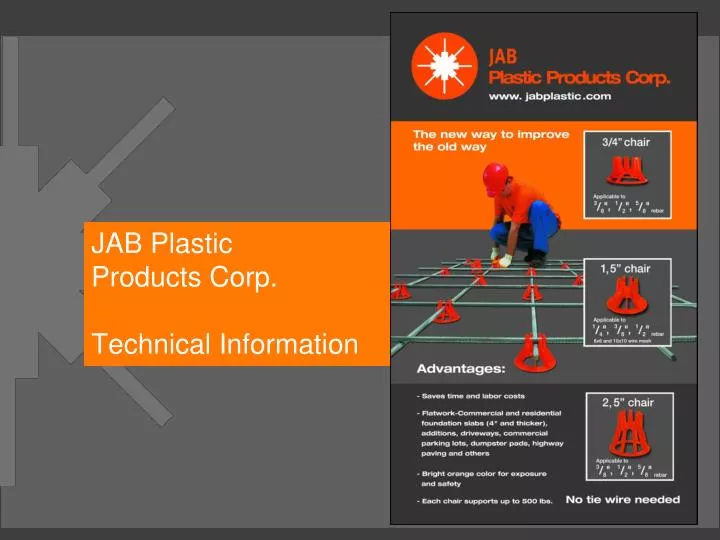
JAB Plastic Products Corp. Technical Information. WHAT DO CURRENT DESIGN CODES, STANDARDS AND MANUALS OF PRACTICE REQUIRE?. UNIFORM BUILDING CODE (UBC) 1997 UBC, VOLUME 2 – STRUCTURAL ENGINEERING DESIGN PROVISIONS. Chapter 19, Section 1907.5 – Placing Reinforcement

E N D
WHAT DO CURRENT DESIGN CODES, STANDARDS AND MANUALS OF PRACTICE REQUIRE?
UNIFORM BUILDING CODE (UBC) 1997 UBC, VOLUME 2 – STRUCTURAL ENGINEERING DESIGN PROVISIONS • Chapter 19, Section 1907.5 – Placing • Reinforcement • Chapter 19, Section 1907.6 – Spacing • Limits for Reinforcement • Chapter 19, Section 1907.7 – Concrete • Protection for reinforcement • Same requirements as for the International • Building Code (IBC)
INTERNATIONAL BUILDING CODE (IBC) • Section 1907.5.1 – Bar Support: • Reinforcement bar shall be accurately • placed and adequately supported before • concrete is placed, and shall be secured • against displacement within tolerances. • Section 1907.5.2 – Tolerances: • For Slab depth, d 8 inches; • d, ± 3/8 inch • concrete cover, – 3/8 inch • For Slab depth, d > 8 inches; • d, ± 1/2 inch • concrete cover, - 1/2 inch • Tolerance for Cover shall not exceed • minus 1/3 the minimum concrete cover • required by the approved plans or • specifications.
IBC REQUIREMENTS, CONT. • Section 1907.6 – • Minimum space between bars in slab must • comply with ACI 318, Section 7.6. • Smin. horizontally or vertically = One Bar • Diameter or 1 inch • Section 1907.7.1 – • Minimum concrete cover for non pre-stressed • cast in place concrete: • Concrete permanently expose and cast • against soil – 3” • Concrete expose to soil or weather: • For #6 through #18 Bar – 2” • For #5 & W31 or D31 or • smaller – 1½”
IBC REQUIREMENTS, CONT. Concrete not expose to weather or in contact with soil: For slab - #11 bar or smaller - ¾ inch AMERICAN ASOCIATION OF STATE HIGHWAY AND TRANSPORTATION OFFICIALS (AASHTO) • Standard Specification, Division I – Design, • Section 8.21 provides a minimum distance • between reinforcement bars:
AMERICAN ASOCIATION OF STATE HIGHWAY AND TRANSPORTATION OFFICIALS (AASHTO), CONT. • For bridges’ cast in place concrete slab: • Smin. = 1½ Bar Diameter or • 1½ Max. Diameter of • Coarse Aggregate or • 1½ inches • Standard Specification, Division I – Design, • Section 8.22, Minimum concrete covers: • Concrete expose to soil or weather: • Primary reinforcement – 2” • Stirrup, tie-up, spiral - 1½”
AMERICAN ASOCIATION OF STATE HIGHWAY AND TRANSPORTATION OFFICIALS (AASHTO), CONT. • Standard Specification, Division I – Design, • Section 8.22, Minimum concrete covers: • Concrete slabs exposed to mild climates: • Negative reinforcement – 2” • Positive reinforcement - 1” • Concrete slabs without positive corrosion • protection and frequently exposed to • deicing salts: • Negative reinforcement – 2½” • Positive reinforcement - 1”
AMERICAN ASOCIATION OF STATE HIGHWAY AND TRANSPORTATION OFFICIALS (AASHTO), CONT. • Standard Specification, Division I – Design, • Section 8.22, Minimum concrete covers: • Concrete slab not expose to weather or • in contact with soil: • Primary reinforcement – 1½” • Stirrup, tie-up, spiral - 1” • Standard Specification, Division II – Const., • Section 9.6, Placing and tie-up of reinforcement • bars – requires: • Tie-up all reinforcement bar intersection • around the perimeter of the steel mat.
AMERICAN ASOCIATION OF STATE HIGHWAY AND TRANSPORTATION OFFICIALS (AASHTO), CONT. • Tie-up every two (2) feet maximum • center to center or at any other • intersection, the greater of the two, • for the rest of the bar intersections. • Section 9.6.2 – “reinforcement bar could • be supported on any approved • mechanism. • Use sufficient supports to maintain the • steel bar in position in order to keep • the distance between bars and forms or • the slab surface within tolerance - ¼ inch • of specified on plans or specifications. • The weight of workers and equipments • must be supported against the forms not • against the reinforcement bars.
MANUALS OF STANDARD PRACTICES IN THE CONSTRUCTION INDUSTRY • CONSTRUCTION INSPECTION MANUAL • FOR REINFORCED CONCRETE STRUCTURES • BY THE AMERICAN CONCRETE INSTITUTE • (ACI SP-2 (99)) • STANDARD PRACTICES FOR REINFORCING • STEEL DETAILING BY THE CONCRETE • REINFORCING STEEL INSTITUTE (CRSI)
MANUALS OF STANDARD PRACTICES IN THE CONSTRUCTION INDUSTRY • Steel rebar shall be firmly supported in place. • Reinforcement supports shall be of adequate • capacity and sufficient chairs be placed at the • right locations to support the reinforcement • steel and the construction loads at which it will • be subject to prevent the sagging of the steel • and reducing the distance between the steel • and the forms or earth base. • Allows the use of plastic chairs among other • materials. Do not use rocks, wood blocks or • other materials not approved for rebar support.
MANUALS OF STANDARD PRACTICES IN THE CONSTRUCTION INDUSTRY • In general, support horizontal bars at every • 5 or 6 feet. • Tie-up intersected steel bar at a maximum • of 2 or 3 feet or every other intersection. • To prevent corrosion and to avoid any • surface stains use plastic chairs or • stainless steel chairs.
STANDARD TESTS PERFORMED ON JAB SNAP-ON & SUPPORT SYSTEM. TEST #1 (COMPRESSION)
STANDARD TESTS PERFORMED ON JAB SNAP-ON & SUPPORT SYSTEM. TEST #2 (SEGREGATION)
Core Sample - Chair 2.5” Core Sample - Chair 1.5” Core Samples
STANDARD TESTS PERFORMED ON JAB SNAP-ON & SUPPORT SYSTEM. TEST #3 (SLAB BENDING)
SLAB BENDING TEST For the test, three (3) reinforced concrete slabs with measurements of ten (10) feet long, four (4) feet wide and four (4) inches thick were built. The objective of the test was to locate the chairs within the slabs in similar conditions to which they will be subjected in everyday use, and load test the slabs to determine if the use of the JAB plastic chairs results in localized cracks or fissures around the chairs or the development of any unexpected crack patterns along the width of the slab. The three (3) specimens built for testing differ from each other in the amount of steel or steel ratio used. For slab number 1, four (4) - #3 rebar were used. For the slab number 2, five (5) - #3 rebar were used. For slab number 3, seven (7) - #3 rebar were used. Based on these parameters, slab #1 should support under service load conditions, 20 pounds/ft2 of live load in addition to its own weight, slab #2 - 30 pounds/ft2 of live load and the slab #3 - 40 pound/ft2 of live load.
Figure 9 – General View of Slab forms, chairs and rebar before pouring concrete Figure 9 illustrates a general view of the specimens showing the location of the plastic chairs and the steel before pouring the concrete. The concrete used for these tests was pre-mixed. The maximum size of the coarse aggregate was ¾” nominal diameter. The average of six (6) cylinders, concrete compressive strength (f’c) was 2,310 psi at 28 days. This f’c was inferior to those normally specified in common construction for structural members (e.g. 3,000 psi).
Figure 10 – Block load application sequence used during the testing Figure 10 shows markings drawn to identify the sequence and the location of the blocks upon the slab. It was designed to simulate a uniform distributed load after all concrete blocks were in placed.
Figure 11 shows one of the reinforced concrete slabs during the loading procedure. Before starting the test, various blocks of 6” x 8” x 16” were weighed and an average weight was calculated to compute the number of blocks needed for each specimen. With an average weight of 30 pounds, 27 blocks were located over slab #1, 40 blocks were located over slab #2 and 54 blocks were located over slab #3 to simulate the corresponding live loads of approximately 20 pounds/ft^2, 30 pounds/ft^2 and 40 pounds/ft^2, respectively. Figure 11 - General View of the Load applied to Slab 1 Figure 12 illustrates the cracks pattern observed during the tests. On each of the slabs, cracks begin to appear after 20 blocks have been placed on the slab. The cracks appear on or near the center and extended all over the width of slab. No crack concentrations were found around the chairs or along the slab where the chairs were located. No crack patterns different from what normally can be found in reinforced concrete slab with steel wire or cement mortar (“limbers”) rebar supports subject to bending were observed. The difference found between each one of the specimens was not in the crack pattern but in the amount of cracks found along the width of the slab and the measurement (width) of the crack. The difference was expected since the load applied was doubled from slab #1 to slab #3. Figure 12 – Crack Pattern on the Central Zone of Slab 3
STANDARD TESTS PERFORMED ONJAB SNAP-ON & SUPPORT SYSTEM.TEST #4 (FILTRATION)
Figure 13 – Arrangement Used during the Filtration Tests Figure 14 – Bottom View of Concrete Slab alter 10 days
Slab Filtration Test With the objective of evaluating if placing the JAB plastic chairs instead of the metallic or mortar supports could contribute to develop a localized filtration condition in the slab, a test was specifically designed to evaluate the effect of the plastic chairs in the filtration pattern. The test consisted in maintaining 1.5 inches of water on the surface of slab for ten (10) days. During this period of time, the filtration pattern was visually observed, evaluating specifically if the water filtration was somehow increased or different around the zones where the plastic chairs were located. Figure 13 shows the arrangement used for the tests. Figure 14 shows that after 10 days of maintaining the top portion of the slab submerge in water, no filtration marks were noticed around the location of the chairs nor along any of the cracks under the slab. The daily observation made under the slab during the preceding 9 days concurs with the final observation at day 10 of the test.
REBAR QUANTITY AND INSTALLATION PATTERNS SHOULD BE AS INDICATED BY THE JAB PLASTIC CHAIR QUANTITY CALCULATOR, BUT FOR THE MOST PART THE FOLLOWING RESTRICTIONS APPLY: TO AVOID SAGGING OF THE REBAR, LOCATE CHAIRS AT A DISTANCE NOT GREATER THAN: FOR #3 OR 3/8” BARS - 2 FEET CENTER TO CENTER FOR #4 OR ½” BARS - 3 FEET CENTER TO CENTER FOR #5 OR 5/8” BARS - 4 FEET CENTER TO CENTER FOR BIGGER BAR NUMBERS, CHAIRS SHALL IN NO EVENT BE LOCATED FARTHER APART THAN 5 OR 6 FEET CENTER TO CENTER TO ELLIMINATE THE USE OF TIE-UP WIRES, LOCATE PLASTIC CHAIRS AT A DISTANCE OF 2 FEET OR LESS CENTER TO CENTER IN BOTH DIRECTIONS JAB SNAP-ON & SUPPORT SYSTEM INSTALLATION PROCEDURES
ALWAYS VERIFY THAT REBARS ARE LOCATED AT THE RIGHT POCKET FOR PROPER GRIP. THE GRIP PROVIDED BY THE SNAP-ON FEATURE OF THE CHAIR IS STRONG ENOUGH TO KEEP REBAR IN PLACE, THEREFORE EXCEEDING CODE REQUIREMENTS. ALWAYS VERIFY THE REQUIREMENTS OF THE CRSI STANDARD PRACTICE OR STEEL DETAILING MANUALS FOR PROPER LOCATION OF THE CHAIRS THERE ARE SPECIFIC AND DIFFERENT REQUIREMENTS FOR EACH TYPE OF STRUCTURAL SLABS AND SLAB ON GRADE JAB SNAP-ON & SUPPORT SYSTEM INSTALLATION PROCEDURES, CONT.
PRODUCTS AVAILABLE FOR DELIVERY NOW! HEAVY DUTY 1.5” INCHES HIGH FOR #2, #3 & #4 REBARS & 6x6-10x10 WIRE MESH HEAVY DUTY 2.5” INCHES HIGH FOR #3, #4 & #5 REBARS
PRODUCTS AVAILABLE FOR DELIVERY NOW! HEAVY DUTY .75” INCHES HIGH FOR #3, #4 & #5 REBARS • DOUBLE MAT SYSTEM FROM 2” TO 8” • FOR #3, #4, #5, #6, #7 & #8 BAR SIZES
PRODUCTS AVAILABLE FOR DELIVERY NOW! STANDARD CROWN 1 (1.5”,2.0”,2.5” and 3.0”) INCHES HIGH FOR #2, #3, #4 REBARS & 6x6-10x10 WIRE MESH . STANDARD CROWN 2 (2.0”to 8” INCHES HIGH FOR #3, #4 and #5 REBARS
PRODUCTS AVAILABLE UPON REQUEST FROM JAB PLASTIC PRODUCTS CORP. • SINGLE MAT CHAIR FROM .75” TO 8” • FOR #3, #4, #5 BAR SIZES • DOUBLE MAT CHAIRS FROM 2” TO 14” • FOR #3, #4, #5, #6, #7 & #8 BAR SIZES
JAB Plastic Snap On and Support System. “The new way to improve the old way” • MEETS CODES/STANDARDS REQUIREMENTS • MEETS STANDARD PRACTICE REQUIREMENTS • SURPASSES EXPECTED CONSTRUCTION LOADS • AVOID CORROSION STAINS • PROVIDES REQUIRED TIE-UP REDUCING LABOR • INTENSIVE COST • COST SAVINGS • COMPETITIVE COST
FOR INFORMATION ABOUT OUR PRODUCTS PLEASE CONTACT: JORGE ALFONSO PRESIDENT CELLULAR PHONE: (210) 859-4110 FAX NUMBER: 1(888) 836-4068
Jab Plastics Chairs Products • 1.5” Plastic Concrete Chair • 2.5” Plastic Concrete Chair • 1/2” Plastic Anchor Bolt Cap • 5/8” Plastic Anchor Bolt Cap The new way to improve the old way JAB PLASTIC PRODUCTS CORP. P.O.Box 11528 Austin , TX 78711-11528 www.jabplastic.com