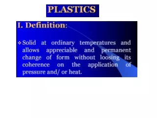
Plastic Products and Processing Methods
Discover the versatility and benefits of plastic products, including thermoplastics and thermosetting plastics. Learn about shaping processes such as compression molding and transfer molding. Explore various plastic types, properties, and typical uses.

Plastic Products and Processing Methods
E N D
Presentation Transcript
Plastic Products • Plastics can be shaped into a wide variety of products: • Molded parts • Extruded sections • Films • Sheets • Insulation coatings on electrical wires • Fibers for textiles More Plastic Products • In addition, plastics are often the principal ingredient in other materials, such as • Paints and varnishes • Adhesives • Various polymer matrix composites • Many plastic shaping processes can be adapted to produce items made of rubbers and polymer matrix composites
Trends in Polymer Processing • Applications of plastics have increased at a much faster rate than either metals or ceramics during the last 50 years • Many parts previously made of metals are now being made of plastics • Plastic containers have been largely substituted for glass bottles and jars • Total volume of polymers (plastics and rubbers) now exceeds that of metals • Almost unlimited variety of part geometries • Plastic molding is a net shape process • Further shaping is not needed • Less energy is required than for metals due to much lower processing temperatures • Handling of product is simplified during production because of lower temperatures • Painting or plating is usually not required
Thermoplastics These plastics are made up of lines of long chain molecules (below) with very few cross linkages. This allows them to soften when heated so that they can be bent into different shapes, and to become stiff and solid again when cooled. This process can be repeated many times. • Thermoplastics • Chemical structure remains unchanged during heating and shaping • More important commercially, comprising more than 70% of total plastics tonnage
Plastic types: Thermoplastics General properties: low melting point, softer, flexible. Typical uses: bottles, food wrappers, toys, … Examples: Polyethylene: packaging, electrical insulation, milk and water bottles, packaging film Polypropylene: carpet fibers, automotive bumpers, microwave containers, prosthetics Polyvinyl chloride (PVC): electrical cables cover, credit cards, car instrument panels Polystyrene: disposable spoons, forks, Styrofoam™ Acrylics (PMMA: polymethyl methacrylate): paints, fake fur, plexiglass Polyamide (nylon): textiles and fabrics, gears, bushing and washers, bearings PET (polyethylene terephthalate): bottles for acidic foods like juices, food trays PTFE (polytetrafluoroethylene): non-stick coating, Gore-Tex™ (raincoats), dental floss
Thermosetting Plastics These plastics are made up of molecules that are heavily cross-linked (below). This results in a rigid molecular structure. Although they soften when heated the first time, and can therefore be shaped, they then become permanently stiff and solid, and cannot be reshaped. • Thermosets • Undergo a curing process during heating and shaping, causing a permanent change (cross‑linking) in molecular structure • Once cured, they cannot be remelted
Plastic types: Thermo sets General properties: more durable, harder, tough, light. Typical uses: automobile parts, construction materials. Examples: Unsaturated Polyesters: lacquers, varnishes, boat hulls, furniture Epoxies and Resins: glues, coating of electrical circuits, composites: fiberglass in helicopter blades, boats, …
SHAPING PROCESSES FOR PLASTICS • Compression Moulding • Transfer Moulding • Extrusion Moulding • Injection Moulding • Blow Moulding • Thermoforming • Calendering • lenPolymer Foam Processing and Forming • Product Design Considerations
compression molding Plastics Processing:Compression Molding
Plastic Processing : Compression Molding Figure : Compression molding for thermosetting plastics: (1) charge is loaded, (2) and (3) charge is compressed and cured, and (4) part is ejected and removed.
Plastic Processing : Compression Molding • Molding materials: • Phenolics, melamine, urea‑formaldehyde, epoxies, urethanes, and elastomers • Typical compression-molded products: • Electric plugs, sockets, and housings; pot handles, and dinnerware plates • Simpler than injection molds • No sprue and runner system in a compression mold • Process itself generally limited to simpler part geometries due to lower flow capabilities of TS materials • Mold must be heated, usually by electric resistance, steam, or hot oil circulation
Plastics Processing:Compression Molding C O M P R E S S I O N M O L D I N G
Transfer Molding TS charge is loaded into a chamber immediately ahead of mold cavity, where it is heated; pressure is then applied to force soft polymer to flow into heated mold where it cures • Two variants: • Pot transfer molding - charge is injected from a "pot" through a vertical sprue channel into cavity • Plunger transfer molding– plunger injects charge from a heated well through channels into cavity.
Transfer Molding Pot Transfer Moulding
Pot Transfer Molding Figure : (a) Pot transfer molding: (1) charge is loaded into pot, (2) softened polymer is pressed into mold cavity and cured, and (3) part is ejected.
Plunger Transfer Molding Figure : (b) plunger transfer molding: (1) charge is loaded into pot, (2) softened polymer is pressed into mold cavity and cured, and (3) part is ejected.
Thermoplastic granules (right) are fed from a hopper by a rotating screw through a heated cylinder. The tapered shape of the screw (right) compacts the plastic as it becomes plasticized. This part of the process is similar to the heating and compacting stages in the injection moulding process. The difference being that the softened material is allowed to flow out through a die in a continuous stream ( Extrusion moulding ) rather than be pumped intermittently in measured amounts into a mould.( Injection moulding ) The die (right) which is fitted to the end of the extruder barrel determines the cross-section of the extrusion.
Extruder Figure : Components and features of a (single‑screw) extruder for plastics Compression process in which material is forced to flow through a die orifice to provide long continuous product whose cross‑sectional shape is determined by the shape of the orifice of a die • Widely used for thermoplastics and elastomers to mass produce items such as tubing, pipes, hose, structural shapes, sheet and film, continuous filaments, and coated electrical wire • Carried out as a continuous process; extrudate is then cut into desired lengths
Extruder Screw • Divided into sections to serve several functions: • Feed section - feedstock is moved from hopper and preheated • Compression section - polymer is transformed into fluid, air mixed with pellets is extracted from melt, and material is compressed • Metering section - melt is homogenized and sufficient pressure developed to pump it through die opening
Die End of Extruder : Extrusion Die for Solid Cross Section Figure : (a) Side view cross‑section of an extrusion die for solid regular shapes, such as round stock; (b) front view of die, with profile of extrudate. • Progress of polymer melt through barrel leads ultimately to the die zone • Before reaching die, the melt passes through a screen pack - series of wire meshes supported by a stiff plate containing small axial holes • Functions of screen pack: • Filter out contaminants and hard lumps • Build pressure in metering section • Straighten flow of polymer melt and remove its "memory" of circular motion from screw
Extrusion Die for Coating Wire Figure : Side view cross‑section of die for coating of electrical wire by extrusion. • Polymer melt is applied to bare wire as it is pulled at high speed through a die • A slight vacuum is drawn between wire and polymer to promote adhesion of coating • Wire provides rigidity during cooling - usually aided by passing coated wire through a water trough • Product is wound onto large spools at speeds up to 50 m/s (10,000 ft/min)
Extrusion This process can be compared to squeezing toothpaste from a tube. It is a continuous process used to produce both solid and hollow products that have a constant cross-section. E.g. window frames, hose pipe, curtain track, garden trellis. Process The photo below shows a typical thermoplastic extruder.
Injection Molding Polymer is heated to a highly plastic state and forced to flow under high pressure into a mold cavity where it solidifies and the molding is then removed from cavity • Produces discrete components almost always to net shape • Typical cycle time 10 to 30 sec, but cycles of one minute or more are not uncommon • Mold may contain multiple cavities, so multiple moldings are produced each cycle Injection Molding Machine • Two principal components: • Injection unit • Melts and delivers polymer melt • Operates much like an extruder • Clamping unit • Opens and closes mold each injection cycle
Plastics Processing : Injection Molding Machine Figure : Diagram of an injection molding machine, reciprocating screw type (some mechanical details are simplified).
Plastics Processing:Injection Molding (2) melt is injected into cavity. (1) mold is closed (4) mold opens and part is ejected. (3) screw is retracted. Cycle of operation for injection molding
* Schematic of thermoplastic Injection molding machine Process & machine schematics *
Blow Molding Molding process in which air pressure is used to inflate soft plastic into a mold cavity • Important for making one‑piece hollow plastic parts with thin walls, such as bottles • Because these items are used for consumer beverages in mass markets, production is typically organized for very high quantities Blow Molding Process • Accomplished in two steps: • Fabrication of a starting tube, called a parison • Inflation of the tube to desired final shape • Forming the parison is accomplished by either • Extrusion or • Injection molding
Extrusion Blow Molding Figure : Extrusion blow molding: (1) extrusion of parison; (2) parison is pinched at the top and sealed at the bottom around a metal blow pin as the two halves of the mold come together; (3) the tube is inflated so that it takes the shape of the mold cavity; and (4) mold is opened to remove the solidified part.
Extrusion Blow Molding • Extrusion Blow Molding involves manufacture of parison by conventional extrusion method using a die similar to that used for extrusion pipes. • Extrusion Blow Molding is commonly used for mass production of plastic bottles. • The production cycle consists of the following steps: • 1.The parison is extruded vertically in downward direction between two mold halves. • 2. When the parison reaches the required length the two mold halves close resulting in pinching the top of parison end and sealing the blow pin in the bottom of the parison end. • 3.Parison is inflated by air blown through the blow pin, taking a shape conforming that of the mold cavity. The parison is then cut on the top. • 4.The mold cools down, its halves open, and the final part is removed.
1 3 4 2
Injection Blow Molding Figure : Injection blow molding: (1) parison is injected molded around a blowing rod; (2) injection mold is opened and parison is transferred to a blow mold; (3) soft polymer is inflated to conform to the blow mold; and (4) blow mold is opened and blown product is removed.
Injection Blow Molding 1. In Injection Blow Molding method a parison is produced by injecting a polymer into a hot injection mold around a blow tube or core rod. 2.Then the blow tube together with the parison is removed from the injection mold and transferred to a blow mold. Following operations are similar to those in the extrusion blowing molding. 3. Injection Blow Molding is more accurate and controllable process as compared to the Extrusion Blow Molding. It allows producing more complicated products from a wider range of polymer materials. 4. However production rate of Injection Blow Molding method is lower than that of Extrusion Blow Molding.
The photo (below) shows fluid containers used in hospitals, ready to be trimmed. A wide variety of colours can be achieved by adding a colouring agent to the mix of thermoplastic granules (about 1% by volume).