Download
1 / 8
90 likes | 285 Vues
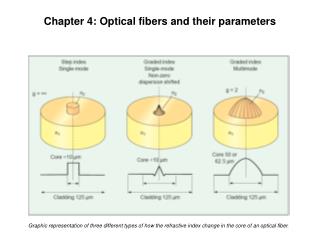
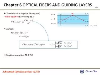
Chapter 6 OPTICAL FIBERS AND GUIDING LAYERS. ◈ The dielectric slab guide (Waveguide) ▪ Wave equation (Governing eq.):. TIR. ▪ Solution:. ▪ Direction separation: TE & TM. Transverse Electric (TE) Modes (1/3). ▪ TE field: ▪ Wave equation (previous):

E N D
Chapter 6 OPTICAL FIBERS AND GUIDING LAYERS ◈ The dielectric slab guide (Waveguide) ▪ Wave equation (Governing eq.): TIR ▪ Solution: ▪ Direction separation: TE & TM
Transverse Electric (TE) Modes (1/3) ▪ TE field: ▪ Wave equation (previous): ▪ We can get the Eigen-value equation: TIR Each eigenfunction has one eigenvalue associated with it, ie, eigenfunctions and eigenvalues come in pairs . ▪ Considering : ▪ For core, we select a symmetric solution:
Transverse Electric (TE) Modes (2/3) ▪ To match the boundary condition, the impedance should be continuous (at the interface): moves toward the origin and intersections are lost ▪ All higher-order modes (m>0) have a cutoff Waves are not guided below a certain critical frequency
Transverse Electric (TE) Modes (3/3) -- Even -- Odd ▪ Let (Normalized term), then the previous solutions are represented as: - even case: - odd case: ▪ [Ex]Higher mode r m=1 ▪ Graphical representation - Discrete # of the TE solutions (modes) - - Mode depends on the radius of the circle m=0 m=2
Dispersion diagram for TE waves in dielectric guide Higher mode Less β
Numerical/Graphical representation ▪ Field profile of dominant mode for three different frequencies ▪ Dominant TE mode
Additional comprehension for waveguide E(y) profile: n1=1.5, n2=1.495, d=10mm, l=1mm TE1 TE2 x Core Cladding Even function solution Odd function solution TE3 → E or energy penetrates (leaks) at the boundary Even function solution TIR backward and forward in x-direction: Standing wave case
Additional comprehension for waveguide ▪ Confinement factor: G - How much power is confined within the core -- Even -- Odd - How does Gchange for different modes? n2 + + n1 r n2 ▪ Partitioning of input field into different guided modes. - Discrete modes Summation of the solutions → Energy penetrates (leaks) at the boundary →