Chapter 8: Optical Fibers and Components
640 likes | 1.09k Vues
Chapter 8: Optical Fibers and Components. TOPICS WDM optical networks Light transmitted through an optical fiber Types of optical fibers Impairments Components: Lasers, optical amplifiers, couplers, OXCs. WDM optical networks. 1. A point-to-point connection. 1. Tx. Rx. …. ….

Chapter 8: Optical Fibers and Components
E N D
Presentation Transcript
Chapter 8:Optical Fibers and Components TOPICS • WDM optical networks • Light transmitted through an optical fiber • Types of optical fibers • Impairments • Components: Lasers, optical amplifiers, couplers, OXCs Connection-Oriented Networks
WDM optical networks 1 A point-to-point connection 1 Tx Rx … … optical fiber optical fiber W Pre- amplifier In-line amplification Power amplifier W Tx Rx Wavelength multiplexer Wavelength demultiplexer Connection-Oriented Networks
Mesh network Ring 4 Ring 1 Ring 2 Ring 3 An example of an optical network Connection-Oriented Networks
How light is transmitted through an optical fiber Waves and electrical fields Wave Electric field Source Connection-Oriented Networks
An optical fiber Cladding Core Cladding • Core and cladding Cladding Cladding Core Core n1 n1 Refractive index Refractive index n2 n2 Radial distance Radial distance • a) Step-index fiber b) graded-index fiber Connection-Oriented Networks
Refraction and reflection of a light ray Refracted ray f n2 n1 r Incident ray Reflected ray Connection-Oriented Networks
Angle of launching a ray into the fiber Cladding Cladding Core Core r l Cladding Cladding Cladding Optical transmitter Core Cladding Connection-Oriented Networks
Multi-mode and single-mode fibers • Core/diameter of a multi-mode fiber: • 50/125 m, • 62.5/125 m, • 100/140 m • Core/diameter of single-mode fiber • 9 or 10 / 125 m Connection-Oriented Networks
Electric fields Cladding A Core 2 1 Cladding B Connection-Oriented Networks
Electric field amplitudes for various fiber modes Cladding Core Cladding m=0 m=1 m=2 Connection-Oriented Networks
Propagation of modes Cladding Cladding a) step-index fiber Cladding Cladding b) Graded-index fiber Connection-Oriented Networks
Cladding Cladding Single-mode fiber Connection-Oriented Networks
Impairments • The transmission of light through an optical fiber is subjected to optical effects, known as impairments. • There are: • linear impairments, and • non-linear impairments. Connection-Oriented Networks
Linear impairments • These impairments are called linear because their effect is proportional to the length of the fiber. • Attenuation: • Attenuation is the decrease of the optical power along the length of the fiber. • Dispersion • Dispersion is the distortion of the shape of a pulse. Connection-Oriented Networks
Attenuation 2.5 2.0 1.5 Attenuation, dB 1.0 0.5 800 1000 1200 1400 1600 1800 Wavelength, nm Connection-Oriented Networks
Attenuation in Fiber • Attenuation • P(L) = 10-AL/10P(0) • Where P(0) optical power at transmitter, • P(L) power at distance L Km, and • A = attenuation constant of the fiber • Received Power must be greater or equal to • receiver sensitivity Pr • Lmax = 10/A log10(P(0)/P(r)) Connection-Oriented Networks
Dispersion • Dispersion is due to a number of reasons, such as • modal dispersion, • chromatic dispersion, • polarization mode dispersion. Connection-Oriented Networks
Time Modal dispersion • In multi-mode fibers some modes travel a longer distance to get to the end of the fiber than others • In view of this, the modes have different delays, which causes a spreading of the output pulse Power Power Power Time Time Connection-Oriented Networks
Chromatic dispersion • It is due to the fact that the refractive index of silica is frequency dependent. In view of this, different frequencies travel at different speeds, and as a result they experience different delays. • These delays cause spreading in the duration of the output pulse. Connection-Oriented Networks
Chromatic dispersion can be corrected using a dispersion compensating fiber. The length of this fiber is proportional to the dispersion of the transmission fiber. Approximately, a spool of 15 km of dispersion compensating fiber is placed for every 80 km of transmission fiber. • Dispersion compensating fiber introduces attenuation of about 0.5 dB/km. Connection-Oriented Networks
Polarization mode dispersion (PMD) • It is due to the fact that the core of the fiber is not perfectly round. • In an ideal circularly symmetric fiber the light gets polarized and it travels along two polarization planes which have the same speed. • When the core of the fiber is not round, the light traveling along the two planes may travel at different speeds. • This difference in speed will cause the pulse to break. Connection-Oriented Networks
Non-linear impairments • They are due to the dependency of the refractive index on the intensity of the applied electrical field. The most important non-linear effects in this category are: self-phase modulation and four-wave mixing. • Another category of non-linear impairments includes the stimulated Raman scattering and stimulated Brillouin scattering. Connection-Oriented Networks
Types of fibers • Multi-mode fibers: They are used in LANs and more recently in 1 Gigabit Ethernet and 10 Gigabit Ethernet. • Single-mode fiber is used for long-distance telephony, CATV, and packet-switched networks. • Plastic optical fibers (POF) Connection-Oriented Networks
Single-mode fibers: • Standard single-mode fiber (SSMF): Most of the installed fiber falls in this category. It was designed to support early long-haul transmission systems, and it has zero dispersion at 1310 nm. • Non-zero dispersion fiber (NZDF):This fiber has zero dispersion near 1450 nm. Connection-Oriented Networks
Negative dispersion fiber (NDF): This type of fiber has a negative dispersion in the region 1300 to 1600 nm. • Low water peak fiber (LWPF): The peak in the attenuation curve at 1385 nm is known as the water peak. With this new type of fiber this peak is eliminated, which allows the use of this region. Connection-Oriented Networks
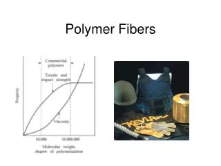
Plastic optical fibers (POF) • Single-mode and multi-mode fibers have a high cost and they require a skilled technician to install them. • POFs on the other hand, are very low-cost and they can be easily installed by an untrained person. • The core has a very large diameter, and it is about 96% of the diameter of the cladding. • Plastic optic fibers find use in digital home appliance interfaces, home networks, and cars Connection-Oriented Networks
Components • Lasers • Photo-detectors and optical receivers • Optical amplifiers • The 2x2 coupler • Optical cross connects (OXC) Connection-Oriented Networks
Light amplification by stimulated emission of radiation (Laser) • A laser is a device that produces a very strong and concentrated beam. • It consists of an energy source which is applied to a lasing material, a substance that emits light in all directions and it can be of gas, solid, or semiconducting material. • The light produced by the lasing material is enhanced using a device such as the Fabry-Perot resonator cavity. Connection-Oriented Networks
Left facet Right facet Fabry-Perot resonator cavity. It consists of two partially reflecting parallel flat mirrors, known as facets, which create an optical feedback that causes the cavity to oscillate. Light hits the right facet and part of it leaves the cavity through the right facet and part of it is reflected. Connection-Oriented Networks
Since there are many resonant wavelengths, the resulting output consists of many wavelengths spread over a few nm, with a gap between two adjacent wavelengths of 100 to 200 GHz. • A single wavelength can be selected by using a filtering mechanism that selects the desired wavelength and provides loss to the other wavelengths. Connection-Oriented Networks
Tunable lasers • Tunable lasers are important to optical networks • Also, it is more convenient to manufacture and stock tunable lasers, than make different lasers for specific wavelengths. • Several different types of tunable lasers exist, varying from slow tunability to fast tunability. Connection-Oriented Networks
Modulation • Modulation is the addition of information on a light stream • This can be realized using the on-off keying (OOK) scheme, whereby the light stream is turned on or off depending whether we want to modulate a 1 or a 0. Connection-Oriented Networks
WDM and dense WDM (DWDM) • WDM or dense WDM (DWDM) are terms used interchangeably. • DWDM refers to the wavelength spacing proposed in the ITU-T G.692 standard in the 1550 nm window (which has the smallest amount of attenuation and it also lies in the band where the Erbium-doped fiber amplifier operates.) • The ITU-T grid is not always followed, since there are many proprietary solutions. Connection-Oriented Networks
The ITU-T DWDM grid Connection-Oriented Networks
Photo-detectors and optical receivers • The WDM optical signal is demultiplexed into the W different wavelengths, and each wavelength is directed to a receiver. • Each receiver consists of a • photodetector, • an amplifier, and • signal-processing circuit. Connection-Oriented Networks
Optical amplifiers • The optical signal looses its power as it propagates through an optical fiber, and after some distance it becomes too weak to be detected. • Optical amplification is used to restore the strength of the signal Connection-Oriented Networks
1 1 Tx Rx … … Amplifiers: power amplifiers, in-line amplifiers, pre-amplifiers optical fiber optical fiber W Pre- amplifier In-line amplification Power amplifier W Tx Rx Wavelength multiplexer Wavelength demultiplexer Connection-Oriented Networks
1R, 2R, 3R • Prior to optical amplifiers, the optical signal was regenerated by first converting it into an electrical signal, then apply • 1R (re-amplification), or • 2R (re-amplification and re-shaping) or • 3R (re-amplification, re-shaping, and re-timing) and then converting the regenerated signal back into the optical domain. Connection-Oriented Networks
Amplification and Regeneration Connection-Oriented Networks
Coupler Signal to be amplified 1550 nm Erbium-doped fiber Isolator Isolator Laser 850 nm The Erbium-doped fiber amplifier (EDFA) Connection-Oriented Networks
Coupler Coupler Signal to be amplified 1550 nm Erbium-doped fiber Isolator Isolator Laser 850 nm Laser 850 nm Two-stage EDFA Connection-Oriented Networks
The 2x2 coupler The 2x2 coupler is a basic device in optical networks, and it can be constructed in variety of different ways. A common construction is the fused-fiber coupler. Fiber 1 Input 1 Output 1 Input 2 Output 2 Fiber 2 Tapered region Coupling region Tapered region Connection-Oriented Networks
3-dB coupler A 2x2 coupler is called a 3-dB coupler when the optical power of an input light applied to, say input 1 of fiber 1, is evenly divided between output 1 and output 2. Connection-Oriented Networks
If we only launch a light to the one of the two inputs of a 3-dB coupler, say input 1, then the coupler acts as a splitter. • If we launch a light to input 1 and a light to input 2 of a 3-dB coupler, then the two lights will be coupled together and the resulting light will be evenly divided between outputs 1 and 2. • In the above case, if we ignore output 2, the 3-dB coupler acts as a combiner. Connection-Oriented Networks
A banyan network of 3-dB couplers 128 1 2 128 3 128 4 128 5 128 6 128 7 128 128 8 Connection-Oriented Networks
Output fibers CPU Input fibers 1 1 W W Fiber 1 Fiber 1 … … 1 1 W W Switchfabric Fiber N Fiber N Optical cross connects (OXCs) Connection-Oriented Networks
OXC (cont’d) • Optical cross-connects Wavelength Router OXC WDM link To & from other nodes To & from other nodes GMPLS Plane UNI Access Station IP router Tx Rx Connection-Oriented Networks Local Add Local Drop
OXC: switching fabric • Switching fabric MEMS: one mirror per output Input WL λ1 to output 1 OXC Output 1 2 3 4 Connection-Oriented Networks
OXC: switching fabric (cont’d) • Switching fabric MEMS: one mirror per output Input WL λ1 to output 4 OXC Output 1 2 3 4 Connection-Oriented Networks
OXC functionality • It switches optically all the incoming wavelengths of the input fibers to the outgoing wavelengths of the output fibers. • For instance, it can switch the optical signal on incoming wavelength i of input fiber k to the outgoing wavelength i of output fiber m. Connection-Oriented Networks