Download
1 / 61
770 likes | 2.32k Vues
CHAPTER 27 Fuel-Injection Components and Operation. OBJECTIVES. After studying Chapter 27, the reader will be able to: Prepare for ASE Engine Performance (A8) certification test content area “C” (Fuel, Air Induction, and Exhaust Systems Diagnosis and Repair).

E N D
CHAPTER 27 Fuel-Injection Components and Operation
OBJECTIVES After studying Chapter 27, the reader will be able to: • Prepare for ASE Engine Performance (A8) certification test content area “C” (Fuel, Air Induction, and Exhaust Systems Diagnosis and Repair). • Describe how a port fuel-injection system works. • Discuss the purpose and function of the fuel-pressure regulator. • List the types of fuel-injection systems.
Demand delivery system (DDS) Electronic air control (EAC) Electronic returnless fuel system (ERFS) Flare Fuel rail Gang fired Idle speed control (ISC) motor Mechanical returnless fuel system (MRFS) Nonchecking Port fuel-injection Pressure control valve (PCV) Pressure vent valve (PVV) Sequential fuel injection (SFI) Throttle-body injection (TBI) KEY TERMS
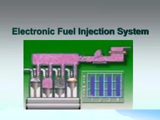
ELECTRONIC FUEL-INJECTION OPERATION • Electronic fuel-injection systems use the computer to control the operation of fuel injectors and other functions based on information sent to the computer from the various sensors. • Most electronic fuel-injection systems share the following: • Electric fuel pump (usually located inside the fuel tank) • Fuel-pump relay (usually controlled by the computer) • Fuel-pressure regulator (mechanically operated springloaded rubber diaphragm maintains proper fuel pressure) • Fuel-injector nozzle or nozzles
FIGURE 27–1 Typical port fuel-injection system, indicating the location of various components. Notice that the fuel-pressure regulator is located on the fuel return side of the system. The computer does not control fuel pressure. But does control the operation of the electric fuel pump (on most systems) and the pulsing on and off of the injectors. ELECTRONIC FUEL-INJECTION OPERATION
ELECTRONIC FUEL-INJECTION OPERATION • Most electronic fuel-injection systems use the computer to control these aspects of their operation: • Pulsing the fuel injectors on and off • Operating the fuel pump relay circuit • There are two types of electronic fuel-injection systems: • Throttle-body-injection (TBI) • Port fuel-injection
“Two Must-Do’s” • For long service life of the fuel system always do the following: • 1. Avoid operating the vehicle on a near-empty tank of fuel. The water or alcohol becomes more concentrated when the fuel level is low. Dirt that settles near the bottom of the fuel tank can be drawn through the fuel system and cause damage to the pump and injector nozzles. • 2. Replace the fuel filter at regular service intervals.
FIGURE 27–2 A dual-nozzle TBI unit on a Chevrolet 4.3-L V-6 engine. The fuel is squirted above the throttle plate where the fuel mixes with air before entering the intake manifold. ELECTRONIC FUEL-INJECTION OPERATION
FIGURE 27–3 A typical port fuel-injection system squirts fuel into the low pressure (vacuum) of the intake manifold, about 3 in. (70 to 100 mm) from the intake valve. ELECTRONIC FUEL-INJECTION OPERATION
SPEED-DENSITY FUEL-INJECTION SYSTEMS • Fuel-injection computer systems require a method for measuring the amount of air the engine is breathing in, in order to match the correct fuel delivery. • There are two basic methods used: • 1. Speed density • 2. Mass airflow • The speed-density method does not require an air quantity sensor, but rather calculates the amount of fuel required by the engine. • The computer uses information from sensors such as the MAP and TP to calculate the needed amount of fuel. • MAP sensor • TP sensor • Temperature sensors
SPEED-DENSITY FUEL-INJECTION SYSTEMS • The formula used to determine the injector pulse width (PW) in milliseconds (ms) is: • Injector pulse width =MAP/BARO xRPM/maximum rpm • The formula is modified by values from other sensors, including: • Throttle position (TP) • Engine coolant temperature (ECT) • Intake air temperature (IAT) • Oxygen sensor voltage (O2S) • Adaptive memory
MASS AIRFLOW FUEL-INJECTION SYSTEMS • The formula used by fuel-injection systems that use a mass airflow (MAF) sensor to calculate the injection base pulse width is: • Injector pulse width =airflow/rpm • The formula is modified by other sensor values such as: • Throttle position • Engine coolant temperature • Barometric pressure • Adaptive memory
THROTTLE-BODY INJECTION • The computer controls injector pulses in one of two ways: • Synchronized • Nonsynchronized • The PCM commands a variety of pulse widths to supply the amount of fuel that an engine needs at any specific moment. • A long pulse width delivers more fuel. • A short pulse width delivers less fuel.
FIGURE 27–4 The tension of the spring in the fuel-pressure regulator determines the operating pressure on a throttle-body fuel-injection unit. THROTTLE-BODY INJECTION
How Do the Sensors Affect the Pulse Width? • The base pulse width of a fuel-injection system is primarily determined by the value of the MAF or MAP sensor and engine speed (RPM). However, the PCM relies on the input from many other sensors to modify the base pulse width as needed. For example, • TP Sensor • ECT • BARO • IAT • O2S
PORT-FUEL INJECTION • The advantages of port fuel-injection design also are related to characteristics of intake manifolds: • Fuel distribution is equal to all cylinders because each cylinder has its own injector. • The fuel is injected almost directly into the combustion chamber, so there is no chance for it to condense on the walls of a cold intake manifold. • Because the manifold does not have to carry fuel to properly position a TBI unit, it can be shaped and sized to tune the intake airflow to achieve specific engine performance characteristics.
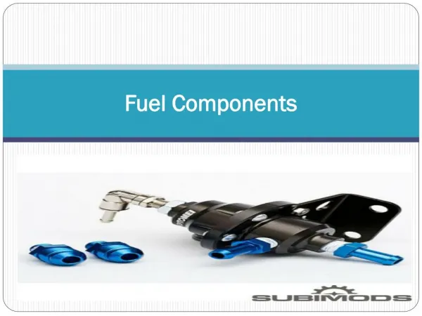
FIGURE 27–5 The injectors receive fuel and are supported by the fuel rail. PORT-FUEL INJECTION
FIGURE 27–6 Cross-section of a typical port fuel-injection nozzle assembly. These injectors are serviced as an assembly only; no part replacement or service is possible except for replacement of external O-ring seals. PORT-FUEL INJECTION
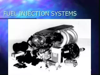
FIGURE 27–7 Port fuel injectors spray atomized fuel into the intake manifold about 3 inches (75 mm) from the intake valve. PORT-FUEL INJECTION • Electronic fuel-injection systems use a solenoid-operated injector to spray atomized fuel in timed pulses into the manifold or near the intake valve.
PORT-FUEL INJECTION • GROUPED DOUBLE-FIRE • SIMULTANEOUS DOUBLE-FIRE • SEQUENTIAL
FIGURE 27–8 A port fuel-injected engine that is equipped with long, tuned intake manifold runners. PORT-FUEL INJECTION
How Can It Be Determined If the Injection System Is Sequential? • Look at the color of the wires at the injectors. If a sequentially fired injector is used, then one wire color (the pulse wire) will be a different color for each injector. The other wire is usually the same color because all injectors receive voltage from some source. If a group- or batch-fired injection system is being used, then the wire colors will be the same for the injectors that are group fired. For example, a V-6 group-fired engine will have three injectors with a pink and blue wire (power and pulse) and the other three will have pink and green wires.
FUEL-PRESSURE REGULATOR • The pressure regulator and fuel pump work together to maintain the required pressure drop at the injector tips. • The fuel-pressure regulator typically consists of a spring-loaded, diaphragm-operated valve in a metal housing. • Fuel-pressure regulators on fuel-return-type fuel-injection systems are installed on the return (downstream) side of the injectors at the end of the fuel rail, or are built into or mounted upon the throttle-body housing.
FIGURE 27–9 A typical port fuel-injected system showing a vacuum-controlled fuel-pressure regulator. FUEL-PRESSURE REGULATOR
FIGURE 27–10 A typical fuel pressure regulator that has a spring that exerts 46 pounds of force against the fuel. If 20 inches of vacuum are applied above the spring, the vacuum reduces the force exerted by the spring on the fuel, allowing the fuel to return to the tank at a lower pressure. FUEL-PRESSURE REGULATOR
Don’t Forget the Regulator • Some fuel-pressure regulators contain a 10-micron filter. If this filter becomes clogged, a lack of fuel flow would result.
FIGURE 27–11 A lack of fuel flow could be due to a restricted fuel-pressure regulator. Notice the fine screen filter. If this filter were to become clogged, higher than normal fuel pressure would occur. Don’t Forget the Regulator
VACUUM-BIASED FUELPRESSURE REGULATOR • The primary reason why many port fuel-injected systems use a vacuum-controlled fuel-pressure regulator is to ensure that there is a constant pressure drop across the injectors. • In a throttle-body fuel-injection system, the injector squirts into the atmospheric pressure regardless of the load on the engine. • In a port fuelinjected engine, however, the pressure inside the intake manifold changes as the load on the engine increases.
ELECTRONIC RETURNLESS FUEL SYSTEM • This system is unique because it does not use a mechanical valve to regulate rail pressure. • Fuel pressure at the rail is sensed by a pressure transducer, which sends a low-level signal to a controller. • The controller contains logic to calculate a signal to the pump power driver. • The power driver contains a high-current transistor that controls the pump speed using pulse width modulation (PWM). • This system is called the electronic returnless fuel system (ERFS).
FIGURE 27–12 The fuel-pressure sensor and fuel-temperature sensor are often constructed together in one assembly to help give the PCM the needed data to control the fuel-pump speed. ELECTRONIC RETURNLESS FUEL SYSTEM
MECHANICAL RETURNLESS FUEL SYSTEM • The first production returnless systems employed the mechanical returnless fuel system (MRFS) approach. • This system has a bypass regulator to control rail pressure that is located in close proximity to the fuel tank. • Fuel is sent by the in-tank pump to a chassis-mounted inline filter with excess fuel returning to the tank through a short return line.
FIGURE 27–13 A mechanical returnless fuel system. The bypass regulator in the fuel tank controls fuel line pressure. MECHANICAL RETURNLESS FUEL SYSTEM
DEMAND DELIVERY SYSTEM (DDS) • Given the experience with both ERFS and MRFS, a need was recognized to develop new returnless technologies that could combine the speed control and constant injector pressure attributes of ERFS together with the cost savings, simplicity, and reliability of MRFS. • This new technology also needed to address pulsation dampening/hammering and fuel transient response. • Therefore, the demand delivery system (DDS) technology was developed.
FIGURE 27–14 A demand delivery system uses an intake regulator. DEMAND DELIVERY SYSTEM (DDS)
Why Are Some Fuel Rails Rectangular Shaped? • A port fuel-injection system uses a pipe or tubes to deliver fuel from the fuel line to the intended fuel injectors. This pipe or tube is called the fuel rail. Some vehicle manufacturers construct the fuel rail in a rectangular cross-section.The sides of the fuel rail are able to move in and out slightly, thereby acting as a fuel pulsator evening out the pressure pulses created by the opening and closing of the injectors to reduce underhood noise. A round cross-section fuel rail is not able to deform and, as a result, some manufacturers have had to use a separate dampener.
FIGURE 27–15 A rectangular-shaped fuel rail is used to help dampen fuel system pulsations and noise caused by the injectors opening and closing. Why Are Some Fuel Rails Rectangular Shaped?
FIGURE 27–16 A multiport fuel injector. Notice that the fuel flows straight through and does not come in contact with the coil windings. FUEL INJECTORS • EFI systems use solenoid-operated injectors.
FIGURE 27–17 Each of the eight injectors shown are producing a correct spray pattern for the applications. While all throttle-body injectors spray a conical pattern, most port fuel injections do not. FUEL INJECTORS
How Can the Proper Injection Size Be Determined? • Most people want to increase the output of fuel to increase engine performance. Injector sizing can sometimes be a challenge, especially if the size of injector is not known. In most cases, manufacturers publish the rating of injectors, in pounds of fuel per hour (lb/hr). The rate is figured with the injector held open at 3 bars (43.5 PSI). An important consideration is that larger flow injectors have a higher minimum flow rating. Here is a formula to calculate injector sizing when changing the mechanical characteristics of an engine.
How Can the Proper Injection Size BeDetermined? • Flow rate =hp xBSFC/# of cylinders xmaximum duty cycle (% of on-time of the injectors) • hp is the projected horsepower. Be realistic! • BSFC is brake-specific fuel consumption in pounds per horsepower-hour. Calculated values are used for this, 0.4 to 0.8 lb. In most cases, start on the low side for naturally aspirated engines and the high side for engines with forced induction. • # of cylinders is actually the number of injectors being used. • Maximum duty cycle is considered at 0.8 (80%). Above this, the injector may overheat, lose consistency, or not work at all.
FIGURE 27–18 A central port fuel-injection system. CENTRAL PORT INJECTION • A cross between port fuel injection and throttle-body injection, CPI was introduced in the early 1990s by General Motors. • The CPI assembly consists of a single fuel injector, a pressure regulator, and six poppet nozzle assemblies with nozzle tubes.
FIGURE 27–19 A factory replacement unit for a CSFI unit that has individual injectors at the ends that go into the intake manifold instead of poppet valves. CENTRAL PORT INJECTION
FUEL-INJECTION MODES OF OPERATION • All fuel-injection systems are designed to supply the correct amount of fuel under a wide range of engine operating conditions. • These modes of operation include: • STARTING MODE • CLEAR FLOOD MODE • OPEN-LOOP MODE • CLOSED-LOOP MODE • ACCELERATION ENRICHMENT MODE • DECELERATION ENLEANMENT MODE • FUEL SHUTOFF MODE
What Is Battery Voltage Correction? • Battery voltage correction is a program built into the PCM that causes the injector pulse width to increase if there is a drop in electrical system voltage. Lower battery voltage would cause the fuel injectors to open slower than normal and the fuel pump to run slower. Both of these conditions can cause the engine to run leaner than normal if the battery voltage is low. Because a lean air–fuel mixture can cause the engine to overheat, the PCM compensates for the lower voltage by adding a percentage to the injector pulse width. This richer condition will help prevent serious engine damage. The idle speed is also increased to turn the generator (alternator) faster if low battery voltage is detected.
FIGURE 27–20 The small arrows indicate the air bypassing the throttle plate in the closed throttle position. This air is called minimum air. The air flowing through the IAC is the airflow that determines the idle speed. IDLE CONTROL • Port fuel-injection systems generally use an auxiliary air bypass.
STEPPER MOTOR OPERATION • A digital output is used to control stepper motors. • Stepper motors are direct-current motors that move in fixed steps or increments from de-energized (no voltage) to fully energized (full voltage). • A stepper motor often has as many as 120 steps of motion.
FIGURE 27–21 Most stepper motors use four wires, which are pulsed by the computer to rotate the armature in steps. STEPPER MOTOR OPERATION
Section Heading • Some Chrysler vehicles, such as the Dodge minivan, use linear solenoid idle air control valves (LSIAC). The PCM uses regulated current flow through the solenoid to control idle speed and the scan tool display is in milliamperes (mA). • Closed position = 180 to 200 mA • Idle = 300 to 450 mA • Light cruise = 500 to 700 mA • Fully open = 900 to 950 mA
SUMMARY • A fuel-injection system includes the electric fuel pump and fuel pump relay, fuel-pressure regulator, and fuel injectors (nozzles). • The two types of fuel-injection systems are the throttle-body design and the port fuel-injection design. • The two methods of fuel-injection control are the speed-density system, which uses the MAP to measure the load on the engine, and the mass airflow, which uses the MAF sensor to directly measure the amount of air entering the engine. • The amount of fuel supplied by fuel injectors is determined by how long they are kept open. This opening time is called the pulse width and is measured in milliseconds.
SUMMARY • The fuel-pressure regulator is usually located on the fuel return on return-type fuel-injection systems. • TBI-type fuel-injection systems do not use a vacuum-controlled fuel-pressure regulator, whereas many port fuel-injection systems use a vacuum-controlled regulator to monitor equal pressure drop across the injectors. • Other fuel designs include the electronic returnless, the mechanical returnless, and the demand delivery systems.