Download
1 / 30
330 likes | 891 Vues
Understand the workings of a port fuel-injection system, sensor influences on pulse width, maintenance tips for fuel system longevity, and component functions. Learn about key factors affecting fuel pressure and injectors.

E N D
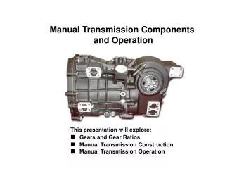
78 FUEL-INJECTION COMPONENTS AND OPERATION
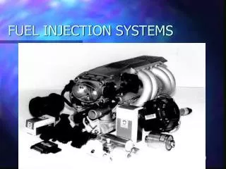
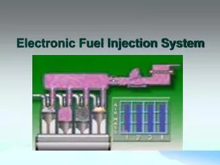
Figure 78-1 Typical port fuel-injection system, indicating the location of various components. Notice that the fuel-pressure regulator is located on the fuel return side of the system. The computer does not control fuel pressure. But does control the operation of the electric fuel pump (on most systems) and the pulsing on and off of the injectors.
Figure 78-2 A dual-nozzle TBI unit on a Chevrolet 4.3-L V-6 engine. The fuel is squirted above the throttle plate where the fuel mixes with air before entering the intake manifold.
Figure 78-3 A typical port fuel-injection system squirts fuel into the low pressure (vacuum) of the intake manifold, about 2 to 3 in. (70 to 100 mm) from the intake valve.
TECH TIP: “Two Must-Do’s” For long service life of the fuel system always do the following: 1. Avoid operating the vehicle on a near-empty tank of fuel. The water or alcohol that may be in the tank becomes more concentrated when the fuel level is low. Dirt that settles near the bottom of the fuel tank can be drawn through the fuel system and cause damage to the pump and injector nozzles. 2. Replace the fuel filter at regular service intervals.
Figure 78-4 The tension of the spring in the fuel-pressure regulator determines the operating pressure on a throttle-body fuel-injection unit.
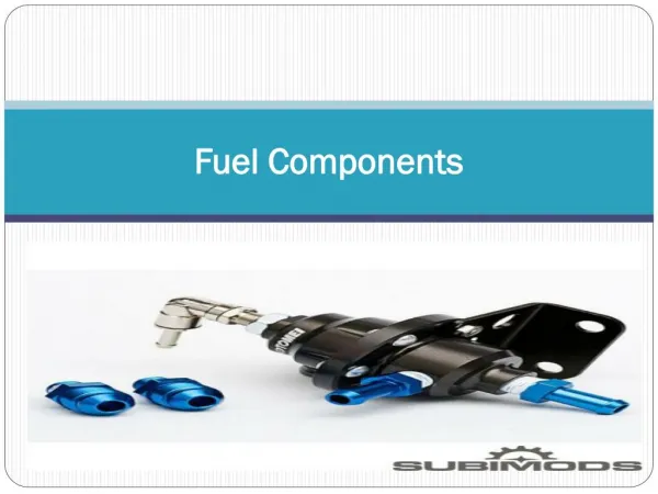
Figure 78-5 The injectors receive fuel and are supported by the fuel rail.
FREQUENTLY ASKED QUESTION: How Do the Sensors Affect the Pulse Width? The base pulse width of a fuel-injection system is primarily determined by the value of the MAF or MAP sensor and engine speed (RPM). However, the PCM relies on the input from many other sensors to modify the base pulse width as needed. For example, • TP Sensor. This sensor causes the PCM to command up to 500% (5 times) the base pulse width if the accelerator pedal is depressed rapidly to the floor. It can also reduce the pulse width by about 70% if the throttle is rapidly closed. • ECT. The value of this sensor determines the temperature of the engine coolant, helps determine the base pulse width, and can account for up to 60% of the determining factors) • BARO. The BARO sensor compensates for altitude and adds up to about 10% under high-pressure conditions and subtracts as much as 50% from the base pulse width at high altitudes. • IAT. The intake air temperature is used to modify the base pulse width based on the temperature of the air entering the engine. It is usually capable of adding as much as 20% if very cold air is entering the engine or reduce the pulse width by up to 20% if very hot air is entering the engine. • O2S. This is one of the main modifiers to the base pulse width and can add or subtract up to about 20% to 25% or more, depending on the oxygen sensor activity.
FREQUENTLY ASKED QUESTION: How Can It Be Determined If the Injection System Is Sequential? Look at the color of the wires at the injectors. If a sequentially fired injector is used, then one wire color (the pulse wire) will be a different color for each injector. The other wire is usually the same color because all injectors receive voltage from some source. If a group- or batch-fired injection system is being used, then the wire colors will be the same for the injectors that are group fired. For example, a V-6 group-fired engine will have three injectors with a pink and blue wire (power and pulse) and the other three will have pink and green wires.
Figure 78-6 Cross-section of a typical port fuel-injection nozzle assembly. These injectors are serviced as an assembly only; no part replacement or service is possible except for replacement of external O-ring seals.
Figure 78-7 Port fuel injectors spray atomized fuel into the intake manifold about 3 inches (75 mm) from the intake valve.
Figure 78-8 A port fuel-injected engine that is equipped with long, tuned intake manifold runners.
Figure 78-9 A typical port fuel-injected system showing a vacuum-controlled fuel-pressure regulator.
Figure 78-10 A typical fuel-pressure regulator that has a spring that exerts 46 pounds of force against the fuel. If 20 inches of vacuum are applied above the spring, the vacuum reduces the force exerted by the spring on the fuel, allowing the fuel to return to the tank at a lower pressure.
TECH TIP: Don’t Forget the Regulator Some fuel-pressure regulators contain a 10-micron filter. If this filter becomes clogged, a lack of fuel flow would result. - SEE FIGURE 78–11 .
Figure 78-11 A lack of fuel flow could be due to a restricted fuel-pressure regulator. Notice the fine screen filter. If this filter were to become clogged, higher than normal fuel pressure would occur.
Figure 78-12 The fuel-pressure sensor and fuel-temperature sensor are often constructed together in one assembly to help give the PCM the needed data to control the fuel-pump speed.
Figure 78-13 A mechanical returnless fuel system. The bypass regulator in the fuel filter controls fuel line pressure.
Figure 78-14 A demand delivery system uses a fuel pressure regulator attached to the fuel pump assembly.
FREQUENTLY ASKED QUESTION: Why Are Some Fuel Rails Rectangular Shaped? A port fuel-injection system uses a pipe or tubes to deliver fuel from the fuel line to the intended fuel injectors. This pipe or tube is called the fuel rail. Some vehicle manufacturers construct the fuel rail in a rectangular crosssection. - SEE FIGURE 78–15 . The sides of the fuel rail are able to move in and out slightly, thereby acting as a fuel pulsator evening out the pressure pulses created by the opening and closing of the injectors to reduce underhood noise. A round cross-section fuel rail is not able to deform and, as a result, some manufacturers have had to use a separate dampener.
Figure 78-15 A rectangular-shaped fuel rail is used to help dampen fuel system pulsations and noise caused by the injectors opening and closing.
Figure 78-16 A multiport fuel injector. Notice that the fuel flows straight through and does not come in contact with the coil windings.
Figure 78-17 Each of the eight injectors shown are producing a correct spray pattern for the applications. While all throttle-body injectors spray a conical pattern, most port fuel injections do not.
Figure 78-19 A factory replacement unit for a CSFI unit that has individual injectors at the ends that go into the intake manifold instead of poppet valves.
FREQUENTLY ASKED QUESTION: How Can the Proper injector Size Be Determined? Most people want to increase the output of fuel to increase engine performance. Injector sizing can sometimes be a challenge, especially if the size of injector is not known. In most cases, manufacturers publish the rating of injectors, in pounds of fuel per hour (lb/hr). The rate is figured with the injector held open at 3 bars (43.5 PSI). An important consideration is that larger flow injectors have a higher minimum flow rating. Here is a formula to calculate injector sizing when changing the mechanical characteristics of an engine. Flow rate = hp X BSFC/# of cylinders X maximum duty cycle (% of on-time of the injectors)• hp is the projected horsepower. Be realistic! • BSFC is brake-specific fuel consumption in pounds per horsepower-hour. Calculated values are used for this, 0.4 to 0.8 lb. In most cases, start on the low side for naturally aspirated engines and the high side for engines with forced induction. • # of cylinders is actually the number of injectors being used. • Maximum duty cycle is considered at 0.8 (80%). Above this, the injector may overheat, lose consistency, or not work at all. For example: 5.7 liter V-8 = 240 hp X 0.65/8 cylinders X 8 = 24.37 lb/hr injectors require
FREQUENTLY ASKED QUESTION: What Is Battery Voltage Correction? Battery voltage correction is a program built into the PCM that causes the injector pulse width to increase if there is a drop in electrical system voltage. Lower battery voltage would cause the fuel injectors to open slower than normal and the fuel pump to run slower. Both of these conditions can cause the engine to run leaner than normal if the battery voltage is low. Because a lean air–fuel mixture can cause the engine to overheat, the PCM compensates for the lower voltage by adding a percentage to the injector pulse width. This richer condition will help prevent serious engine damage. The idle speed is also increased to turn the alternator faster if low battery voltage is detected.
Figure 78-20 The small arrows indicate the air bypassing the throttle plate in the closed throttle position. This air is called minimum air. The air flowing through the IAC (blue arrows) is the airflow that determines the idle speed.
FREQUENTLY ASKED QUESTION: Why Does the Idle Air Control Valve Use Milliamperes? Some Chrysler vehicles, such as the Dodge minivan, use linear solenoid idle air control valves (LSIAC). The PCM uses regulated current flow through the solenoid to control idle speed and the scan tool display is in milliamperes (mA). Closed position = 180 to 200 mA Idle = 300 to 450 mA Light cruise = 500 to 700 mA Fully open = 900 to 950 mA
Figure 78-21 Most stepper motors use four wires, which are pulsed by the computer to rotate the armature in steps.